M2 Z30 20CrMo hammasvõll - H8 variant
20CrMo M2 Z30 välishammasvõll 30° survenurgaga, karastatud ja karastatud kõvadusega HRC58-62 tõmbega juhitavate põllumajanduslike käigukastide liideste jaoks.
M2 Z30 20CrMo hammasvõll - H8 variant — This M2 Z30 20CrMo spline shaft uses a 30-tooth external spline with M2 module and 30° pressure angle. The specified material is 20CrMo, with carburizing and quenching to HRC58-62. This configuration is intended for agricultural machinery drive-shaft applications. The final major and minor diameters, spline length, total length and mating fit are established by the approved drawing.
Toote ülevaade
This M2 Z30 20CrMo spline shaft uses a 30-tooth external spline with M2 module and 30° pressure angle. The specified material is 20CrMo, with carburizing and quenching to HRC58-62. This configuration is intended for agricultural machinery drive-shaft applications. The final major and minor diameters, spline length, total length and mating fit are established by the approved drawing.
Pakkumise saamiseks defineerige hammaslatt osana terviklikust ühenduskohast. Hammaste geomeetria, külgnevad laagrikaelad, õlad, sooned, keermed ja laagripesad tuleks mõõtmestada funktsionaalsete tugipunktide põhjal, et valmisvõlli saaks kontrollida samas suhtes, milles see töötab. Sellel lehel loetlemata mõõtmed on valmistatud kliendi poolt heakskiidetud joonise järgi.
Tehnilised andmed
Allolevad väärtused kirjeldavad seda tootekonfiguratsiooni. Kõik mõõtmed, tolerants, nimiväärtus või sobivus, mida pole näidatud, tuleks enne tootmist päringujoonisel ära märkida.
| Moodul | M2 |
|---|---|
| Hammaste arv | Z30 |
| Rõhu nurk | 30 kraadi |
| Materjal | 20CrMo |
| Täppisnimetus | ISO-H8 |
| Kuumtöötlus | Karboniseeritud ja kustutatud |
| Kõvadus | HRC58-62 |
| Taotlus | Põllumajandustehnika veovõll |
Spline'i geomeetria ja paaritusliides
Hammasratast ei saa valida ainult võlli nimiläbimõõdu põhjal. Kinnitage moodul või sammusüsteem, hammaste arv, rõhunurk, suuremad ja väiksemad läbimõõdud, efektiivne haardumine, hamba paksus või vahe-laiuse alus, otsa reljeef ja vajalik sobivus vastaselemendiga. Kui ühendus on ette nähtud aksiaalselt libisema, märkige ka käik, määrimismeetod ja lubatud lõtk. Kui see on fikseeritud, määrake aksiaalne asukoht ja omadused, mis kannavad või reageerivad tõukejõule.
Tugipunktide seosed on olulised alati, kui hammaslatt töötab laagripessa, hammasrattale, tihendi maanduspunktile või tugiõlale. Hambakuju võib individuaalselt olla tolerantsi piires, kuid tekitada siiski ebaühtlast kontakti, kui hammaslati telge funktsionaalsete hammaslaagide suhtes ei kontrollita. Esitage joonisele viske, asukoha või kontsentrilisuse nõuded ainult siis, kui need kaitsevad montaaži toimivust, ja määrake nii töötlemiseks kui ka kontrollimiseks kasutatav tugipunkt.
Materjal, kuumtöötlus ja pinnaseisukord
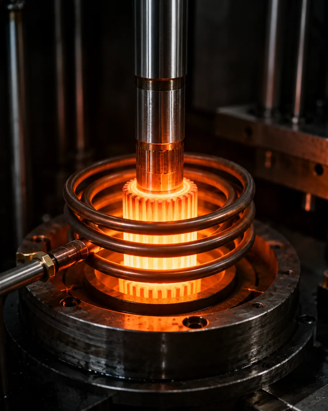
The carburized-and-quenched condition is intended to provide a hard working surface while retaining a different core condition than the case. The listed HRC58-62 value should therefore be tied to a defined inspection location. If case depth, retained core hardness or post-heat-treatment finishing is required, show those requirements on the drawing.
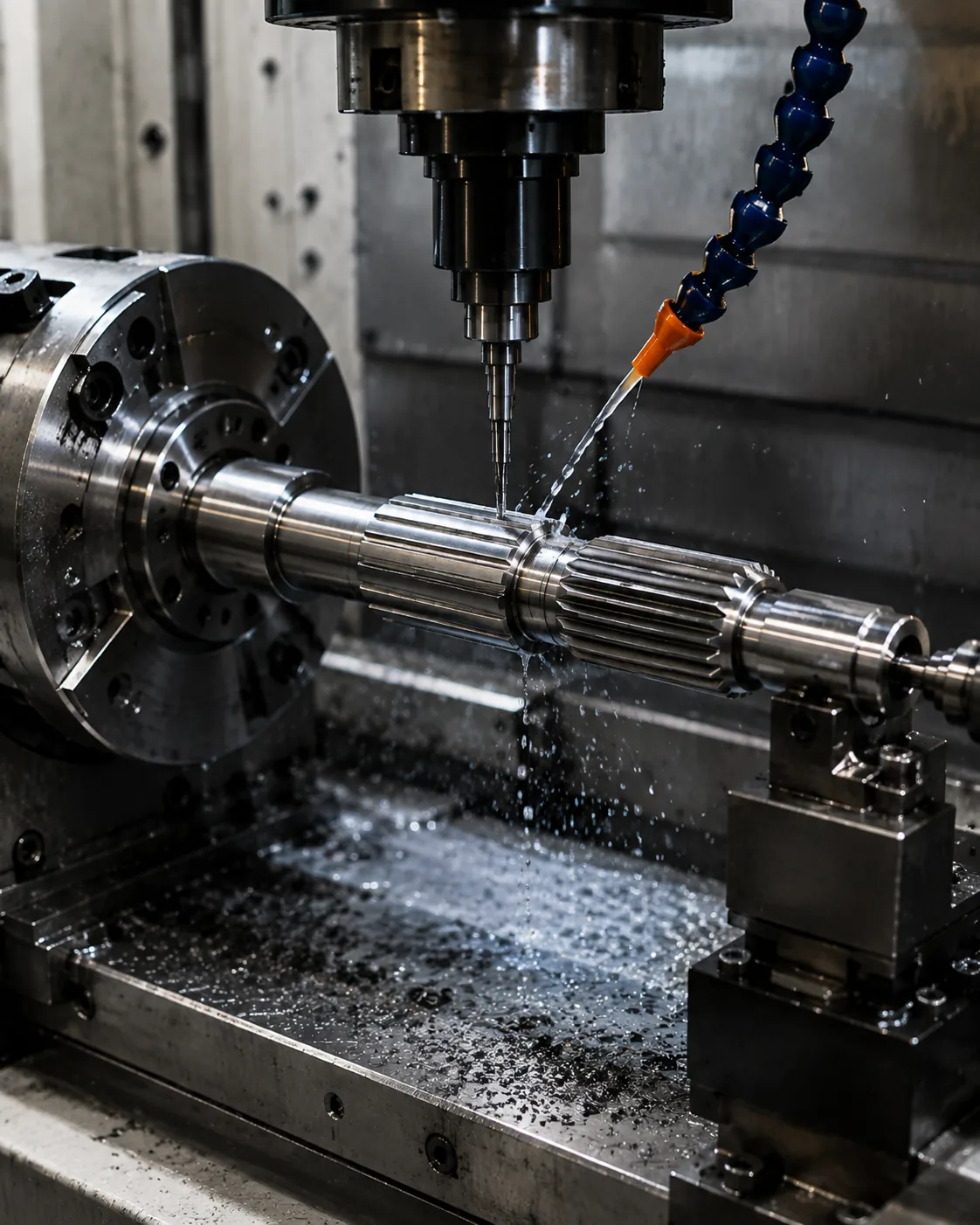
Materjali seisukorda, kuumtöötlust ja viimistlust tuleks vaadelda ühe protsessiahelana. Kuumtöötlusele eelnev jämetöötlus võib jätta tooriku hilisemaks viimistlemiseks; termiline töötlemine võib muuta suurust või sirgust; lõplik lihvimine või kõvaviimistlus võib olla vajalik ainult nende detailide puhul, mille tolerants või pinnaseisund seda nõuab. Määrake valmistoodangu nõuded, mitte ette kirjutage mittevajalikku protsessi, välja arvatud juhul, kui protsess ise on osa kinnitatud projektist.
Taotluse ja kohustuse läbivaatamine
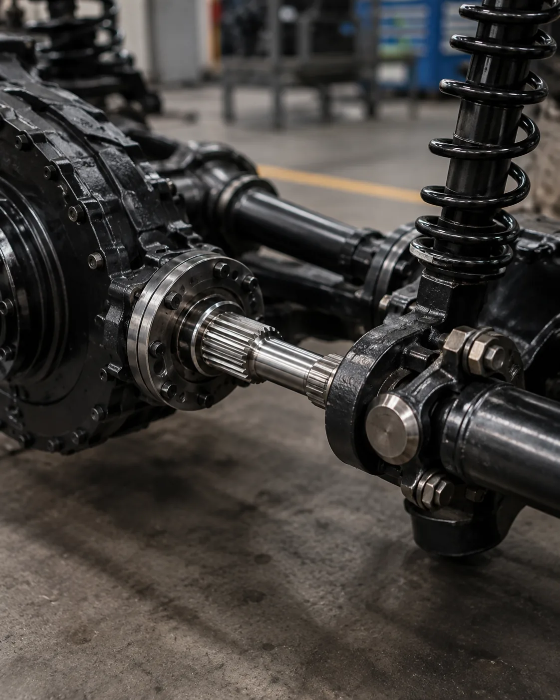
Agricultural transmission interfaces can see shock, repeated load cycles, dirt and changing lubrication conditions. Confirm the connection type, mating spline, engagement length and duty before ordering. A replacement shaft should be checked against the mating member because wear can change the apparent tooth thickness or clearance of the removed part.
Uue konstruktsiooni puhul jagage eeldatavat pidevat ja tippmomenti, kiirusvahemikku, töötsüklit, löögi- või tagasipööratavat koormust, võlliga koosmõjul olevaid radiaal- või aksiaalkoormusi, määrimist ja keskkonnamõjusid. Asenduskomponendi puhul lisage vastasosa ja kulumismustrite fotod. Hõõrdumine, asümmeetriline küljepoleering, süvend või lõtvus võivad viidata joondamise, sobivuse või määrimise probleemidele, mis tuleks enne asendusgeomeetria lõplikku valmimist parandada.
Kontroll ja kvaliteediplaneerimine
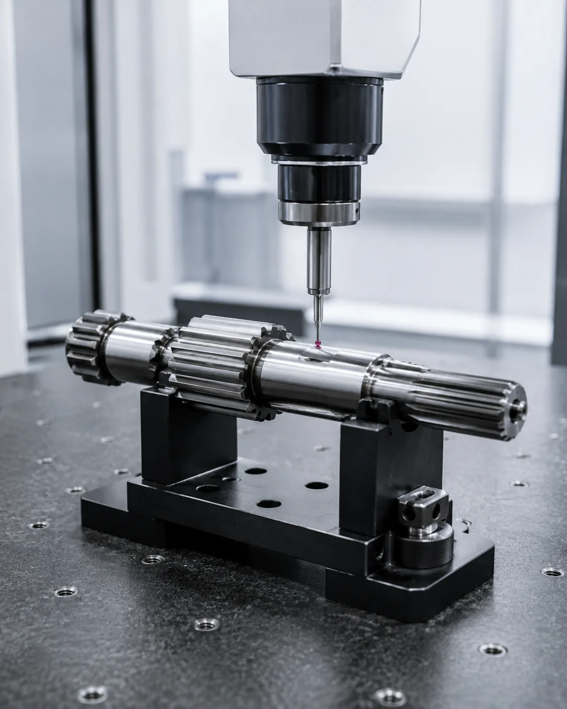
Kontroll peaks olema seotud omadustega, mis kontrollivad montaaži ja pöördemomendi ülekannet. Sõltuvalt jooniselt võib see hõlmata funktsionaalset hammaste mõõtmist, analüütilist hammaste mõõtmist, CMM-i kontrolle, mõõtmist tihvtide või kuulide kohal (kui see on asjakohane), viskekontrolli, pinnakareduse mõõtmist ja kõvaduse testimist. Mõõtmismeetod peaks vastama tolerantsi määratlusele, et tarnija ja klient hindaksid sama omadust samal viisil.
Kuumtöödeldud võllide puhul tuleb kindlaks teha kõvaduse asukoht ja see, kas nõue puudutab ainult pinna kõvadust või ka korpuse sügavust ja südamiku seisukorda. Integreeritud hammasrataste ja hammasliistudega osade puhul tuleb planeerida hammassüsteemide ja laagrite vahelise seose kontrollimist, mitte iga omaduse eraldi kontrollimist. Esimese artikli aruanded peaksid keskenduma kriitilistele joonise omadustele, mis näitavad sobivust ja funktsionaalset joondust.
Kohandamise ja joonistamise kontroll-leht
Ever-Power saab hinnata kohandatud geomeetriat kontrollitud joonise või mõõtmetega liidese definitsiooni põhjal. Pakkumise koostamiseks palun lisage allolevad punktid, mis kehtivad teie koostu kohta:
- 2D joonis koos revisjonitaseme, tugipunktide ja täieliku splaini definitsiooniga
- Vastav rummu, hülsi, hammasratta või hargi geomeetria ja vajalik fikseeritud või libisev sobivus
- Materjali klass, kuumtöötlustingimused, kõvadus ja funktsionaalse pinnaviimistluse nõuded
- Pöördemoment, kiirus, löök- või tagasipööratav koormus, töötsükkel, määrimine ja töökeskkond
- Kriitilise viske, kontsentrilisuse, aksiaalse asukoha ja laagri või tihendi liidese nõuded
- Tellimuse kogus, prototüübi või esimese artikli nõue ja taotletud kontrolldokumentatsioon
For this configuration, please also confirm: Overall dimensions; spline major and minor diameter; effective spline length; torque; speed; Controlled drawing; standard basis and interpretation of the H8 designation.
Võrdle seotud valikuid Välised hammasvõllid vahemikku või kasutage Spline-võlli joonise kontroll-leht enne hinnapäringu esitamist.
Paigaldus-, hooldus- ja rikkeohu kontrollid
Enne kokkupanekut veenduge, et mõlemad vastaselemendid on puhtad, kahjustamata ja mõõtmetega ühilduvad. Ärge rakendage jõudu hammasühendusele, mis haakumise ajal kinni kiilub; uurige enne kokkupanemisjõu rakendamist ebatasasusi, joondust, sobivust ja vahet. Kui määrimine on vajalik, kasutage masina või jõuülekande jaoks määratud määrdeainet ja hooldusintervalli, mitte valige määrdeaine ainult võlli materjali põhjal.
Hoolduse ajal kontrollige hõõrdumisprahti, süvendeid, ebanormaalset külgpoleerimist, korrosiooni, lõtku ja lõtku muutusi. Need sümptomid võivad pärineda võllist, vastaselemendist, tugilaagritest või sõlme joondamisest. Ainult nähtavalt kulunud osa asendamine ilma vastasühendust kontrollimata võib põhjustada sama rikkemehhanismi jätkumist.
Korduva tootmise disainiülevaate märkmed
Korduvus sõltub enamast kui lihtsalt nominaalsest hammasratta suurusest. Hoidke joonise muudatused, vastastikused komponendid, tugiskeemid ja kokkulepitud kontrollimeetodid konfiguratsioonikontrolli all. Kui vastastikused rummud, laagrite paigutus, kuumtöötlus või tööülesanded muutuvad, vaadake liides uuesti üle, sest füüsiliselt sobiv võll ei pruugi säilitada sama kokkupuutemustrit, kliirensit ega koormuse jaotust.
Kui ühel võllil toodetakse mitu detaili, peaks tolerantside jaotus vastama funktsioonile. Laagripesad kontrollivad tavaliselt pöörlemist, õlad kontrollivad aksiaalset asukohta ja hammas- või hammasrattadetailid kannavad üle pöördemomenti. Joonisel peaksid need seosed olema nähtavad, et tootmisplaan saaks kasutada stabiilseid tugipunkte ja kontrollplaan saaks taasesitada montaažiloogikat. See on eriti oluline pärast kuumtöötlust, kui sirgus või detailide suhe võib muutuda ja valitud pindadel võib olla vaja teha lõplikku viimistlust.
Hanke puhul tuleks vältida protsessi üksikasjade täpsustamist, mis ei kaitse funktsionaalset nõuet. Tarnija võib valida erinevaid tööriistade või masinate järjestusi, saavutades samal ajal sama lõpptulemuse. Keskenduge pakkumiskutses mõõdetavatele vastuvõtukriteeriumidele: materjal, kuumtöötlus, kõvadus, hamba geomeetria, sobivus, läbijooks, pinnaviimistlus, mõõtmed ja nõutavad aruanded. See hoiab hinnapakkumised võrreldavad, võimaldades samal ajal tõhusat protsessi.
Tootmisjooniste nõuded
Tootmiseks tuleb määratleda kogu ühendusliides, mitte ainult nimihammaste suurus. Joonisel peaks olema näidatud hammassüsteem, efektiivne haardumine, kogupikkus, külgnevad teljekaelad ja õlad, tugipunktide viited, nõutav vise, materjali seisukord ja mis tahes funktsionaalne pinnaviimistlus. Kui osa peab asendama olemasolevat võlli, tuleb märkida, millised mõõtmed on mõõdetud kulumata osade põhjal, ja esitada ühendusrummu, hülsi, hargi või hammasratta teave, kui see on saadaval.
Samuti esitage tehnilist ülevaadet mõjutav tööinfo: edastatud pöördemoment, pöörlemiskiirus, tagasikäigu- või löögikoormus, määrimine, saastumine, temperatuur, aksiaalne liikumine ja eeldatav montaažimeetod. Need sisendid aitavad tootmis- ja kontrolliplaani tegeliku ühendusega vastavusse viia. Joonisel tuleks tuvastada kriitilised kontrolliomadused, et sama vastuvõtualust saaks kasutada nii esimeste artiklite kui ka korduvate tellimuste puhul.
Korduma kippuvad küsimused
Need küsimused hõlmavad teavet, mida on kõige sagedamini vaja, et muuta hammasvõlli päring tootmiskõlblikuks ja kontrollitavaks jooniseks.
Millist teavet on vaja enne selle hammasvõlli hinnapakkumise esitamist?
Saatke kontrollitud joonis, kogus, paaritusnööri teave, materjali ja kuumtöötluse nõuded, pöördemoment ja kiirus, töökeskkond ning vajalikud kontrolldokumendid. Kui joonis on mittetäielik, tuvastage puudulikud mõõtmed, et need saaks enne tootmist tehnilise ülevaatuse käigus lahendada.
Kas spline'i geomeetriat saab kohandada?
Jah, kohandatud moodulit või sammu, hammaste arvu, rõhunurka, läbimõõte, haardumist ja külgnevaid võlli omadusi saab hinnata vastastikuse liidese ja töökoormuse põhjal. Kõik hamba geomeetria muudatused tuleb kontrollida vastastikuse elemendi suhtes, kuna need muudavad sobivust, kontakti ja vahetatavust.
Kuidas tuleks kõvadust määrata?
Esitage kõvaduse väärtus koos mõõtmiskohaga ja vajadusel ka korpuse sügavuse või südamiku nõuetega. Üks kõvadusnumber ei määra automaatselt kogu võlli seisukorda, eriti kui kasutatakse lokaliseeritud või korpuse karastamise protsesse.
Kuidas peaks väljavoolu kontrollima?
Seo viskeulatus funktsionaalse tugipunktiga, näiteks laagrikaela, juhthammasratta läbimõõdu või hammasratta viitenumbriga. Tolerants peaks kaitsma sõlme ja kontakti, mitte olema lihtsalt võimalikult tihe. Näidake joonisel tugipunkti ja mõõtmistingimusi.
Mida tuleks kulunud võlli vahetamisel kontrollida?
Kontrollige nii vastasrummu või -hülsi kui ka võlli. Mõõtke võimaluse korral kulumata alasid ja dokumenteerige hõõrdumised, süvendid, asümmeetriline kontakt või lõtvus. Need tähelepanekud aitavad eristada normaalset kulumist sobivus-, joondamis- või määrimisprobleemidest.
Küsi hinnapakkumist
- Kontrollitud joonistamine ja redigeerimine
- Paaritusspline'i/liidese teave
- Materjali ja kuumtöötluse nõuded
- Tööülesanded ja keskkond
- Koguse ja kontrolli dokumentatsioon
Saatke joonis ja rakenduse üksikasjad alloleva päringuvormi kaudu. Tehniline ülevaade keskendub ühenduskohale, materjali seisukorrale, funktsionaalsetele andmetele, tööülesannetele ja kontrollinõuetele, seega põhineb hinnapakkumine tegelikul komponendi määratlusel.
Küsi tehnilist hinnapakkumist
Saatke joonis, vastassuunaline hammasratas, materjali seisukord, kogus, pöördemomendi/kiiruse teave ja kontrollinõuded.