18CrNiMo7-6 Vaihde- ja ura-akseli
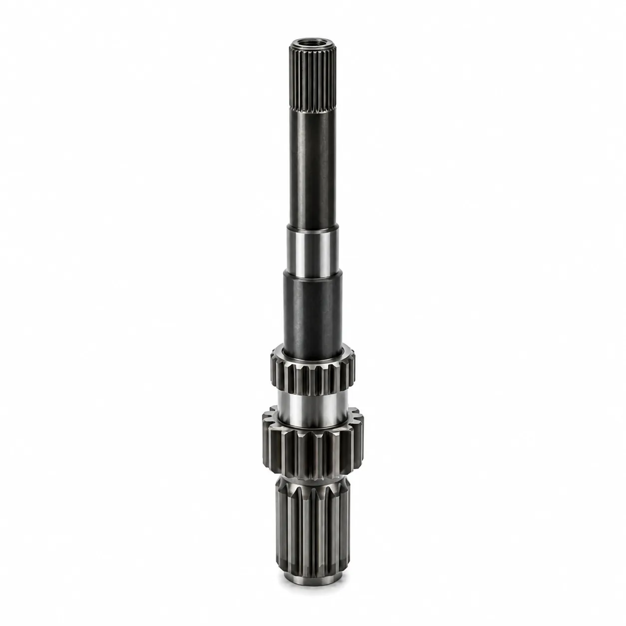
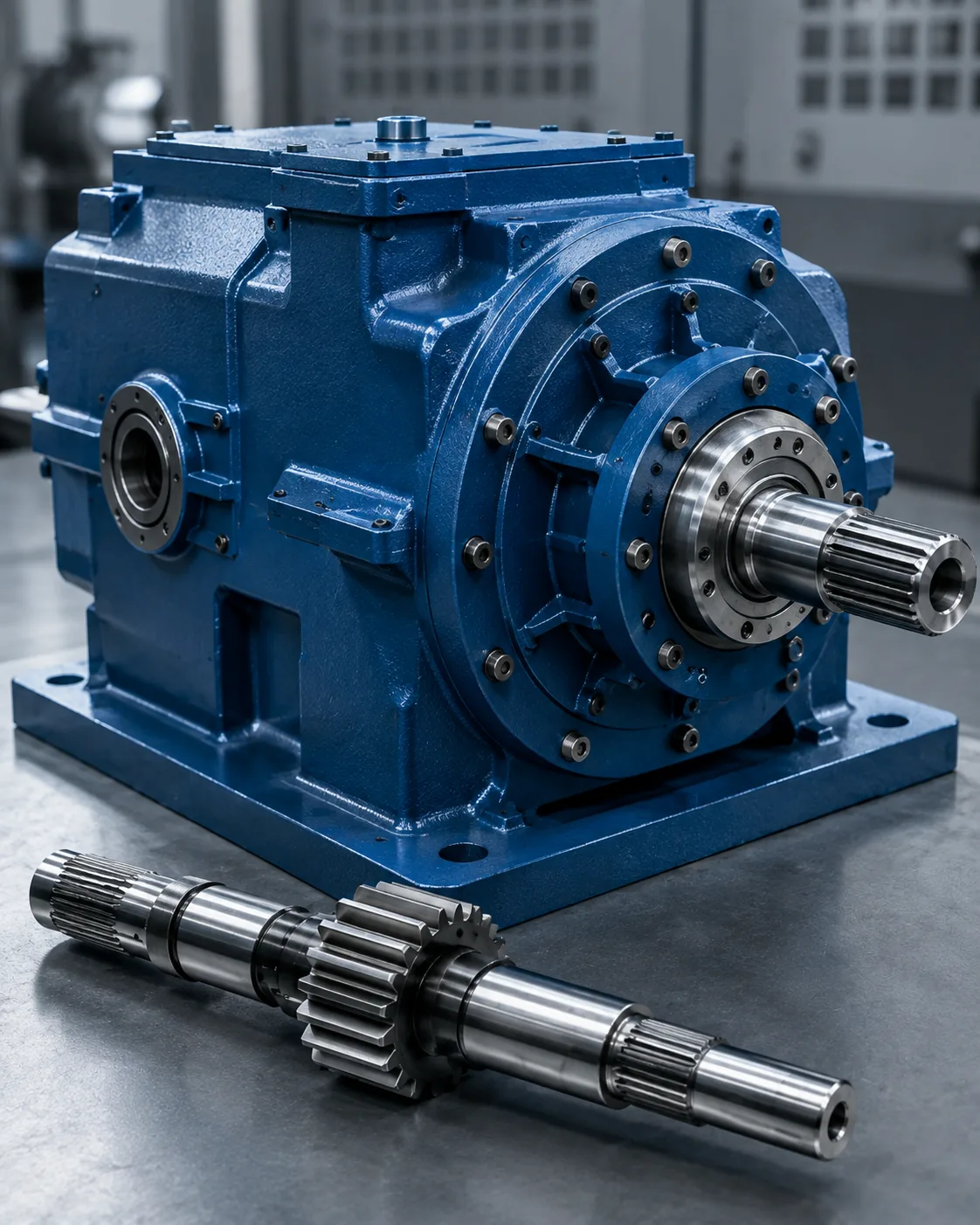
Integroitu 18CrNiMo7-6 hammaspyörä ja ura-akseli, kokonaispituus 758 mm, M5 Z18 hammaspyörä ja M2.5 Z28 ura; hiiletetty ja karkaistu HRC59-63-karkeuteen.
18CrNiMo7-6 Vaihde- ja ura-akseli — 18CrNiMo7-6-hammaspyörä- ja ura-akseli yhdistää M5 Z18 -hammaspyörän ja M2.5 Z28 -ura-akselin yhdelle 758 mm pitkälle akselille. Määritelty materiaali on 18CrNiMo7-6, joka on hiiletetty ja karkaistu HRC59-63-lujuuteen. Hammaspyörän ja ura-akselin integrointi yhdeksi komponentiksi tekee hampaiden ominaisuuksien, laakeritappien ja akselin datapisteiden välisestä suhteesta erityisen tärkeän tuotantopiirustuksen ja tarkastussuunnitelman kannalta.
Tuotteen yleiskatsaus
18CrNiMo7-6-hammaspyörä- ja ura-akseli yhdistää M5 Z18 -hammaspyörän ja M2.5 Z28 -ura-akselin yhdelle 758 mm pitkälle akselille. Määritelty materiaali on 18CrNiMo7-6, joka on hiiletetty ja karkaistu HRC59-63-lujuuteen. Hammaspyörän ja ura-akselin integrointi yhdeksi komponentiksi tekee hampaiden ominaisuuksien, laakeritappien ja akselin datapisteiden välisestä suhteesta erityisen tärkeän tuotantopiirustuksen ja tarkastussuunnitelman kannalta.
Tarjousta varten määrittele ura osaksi täydellistä liitospintaa. Hammasgeometria, vierekkäiset laakeritapit, olkapäät, urat, kierteet ja laakeripesät tulee mitoittaa toiminnallisista viitepisteistä, jotta valmista akselia voidaan tarkastaa samassa suhteessa, jossa se toimii. Tällä sivulla mainitsemattomat mitat valmistetaan asiakkaan hyväksymän piirustuksen mukaan.
Tekniset tiedot
Alla olevat arvot kuvaavat tätä tuotekokoonpanoa. Kaikki mitat, toleranssit, nimellisarvot tai sopivuudet, joita ei ole esitetty, tulee ilmoittaa kyselypiirustuksissa ennen tuotantoa.
| Materiaali | 18CrNiMo7-6 |
|---|---|
| Lämpökäsittely | Hiiletetty ja sammutettu |
| Kovuus | HRC59-63 |
| Kokonaispituus | 758 mm |
| Varusteet | M5 Z18 |
| Spline | M2.5 Z28 |
Spline-geometria ja liitoskohta
Uraa ei voida valita pelkästään nimellisakselin halkaisijan perusteella. Vahvista moduuli tai jakojärjestelmä, hammaslukumäärä, puristuskulma, pää- ja sivuhalkaisijat, tehokas kosketus, hampaan paksuus tai tilan ja leveyden suhde, päätypoikkeama ja vaadittu sovitus vastakappaleeseen. Jos liitoksen on tarkoitus liukua aksiaalisesti, ilmoita myös liikerata, voitelumenetelmä ja sallittu välys. Jos se on kiinteä, määrittele aksiaalinen sijainti ja työntövoimaa kuljettavat tai siihen reagoivat ominaisuudet.
Tietopisteiden suhteilla on merkitystä aina, kun ura-akseli toimii laakerin istukan, hammaspyörän, tiivisteen liitoskohdan tai ohjausolkapään kanssa. Hampaan muoto voi olla yksittäin toleranssin rajoissa, mutta silti se voi aiheuttaa epätasaisen kosketuksen, jos ura-akselia ei ohjata toiminnallisiin laakeritappeihin nähden. Kirjoita piirustukseen heitto-, sijainti- tai samankeskisyysvaatimukset vain, jos ne suojaavat kokoonpanon suorituskykyä, ja määritä sekä koneistuksessa että tarkastuksessa käytetty tietopiste.
Materiaali, lämpökäsittely ja pinnan kunto
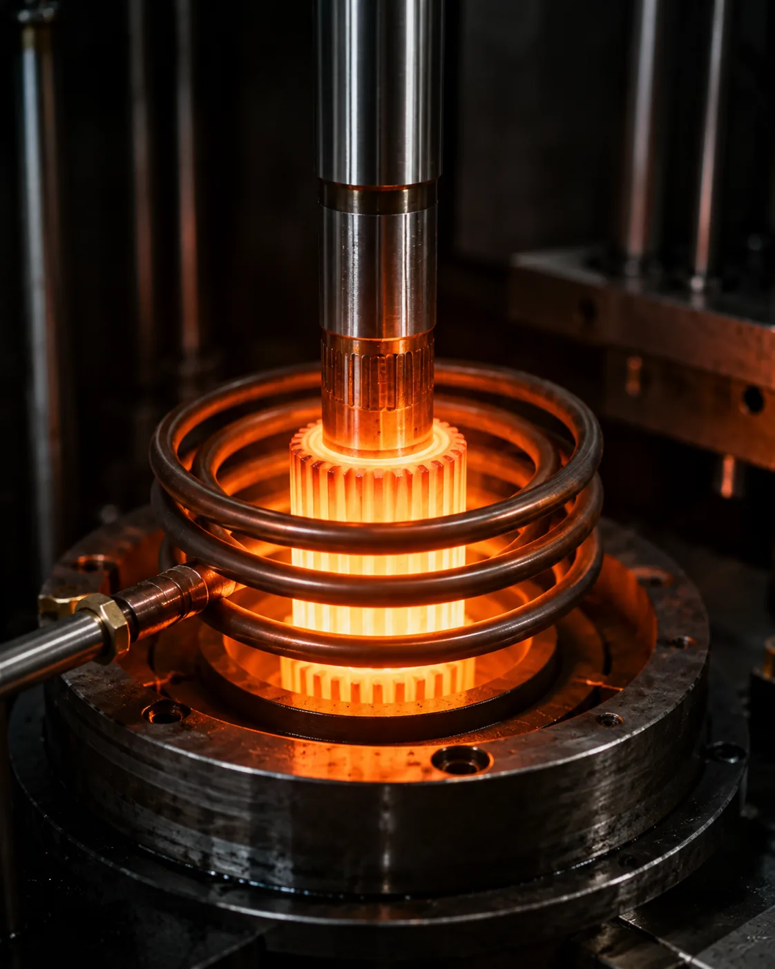
Tässä määritellään 18CrNiMo7-6, jonka hiiletys ja sammutus on HRC59-63. Pitkät, monipiirteiset akselit vaativat lämpökäsittely- ja viimeistelysuunnitelmia, joissa otetaan huomioon muodonmuutokset ja useiden toiminnallisten halkaisijoiden välinen suhde. Jos kotelon syvyys, keernan kunto, hampaan viimeistely tai laakerin hionta on tarpeen, määrittele nämä ominaisuudet piirustuksessa ja merkitse niiden tarkastuskohdat.
Materiaalin kunto, lämpökäsittely ja viimeistely tulisi tarkastella yhtenä prosessiketjuna. Karkea työstö ennen lämpökäsittelyä voi jättää jäljelle varastoa myöhempää viimeistelyä varten; lämpökäsittely voi muuttaa kokoa tai suoruutta; loppuhionta tai kovaviimeistely voi olla tarpeen vain kohdille, joiden toleranssi tai pinnan kunto sitä vaatii. Ilmoita valmiin tuotteen vaatimus sen sijaan, että määräät tarpeettoman prosessin, ellei prosessi itsessään ole osa hyväksyttyä suunnittelua.
Hakemus ja tullin tarkistus
Tämä integroitu asettelu voi vähentää erillisten vääntömomentinsiirtokomponenttien määrää vaihteistokokoonpanossa, mutta tarkka sovellus riippuu vaihteiston geometriasta, urasovituksesta, laakerin tuennasta, kuormitusreitistä ja nopeudesta. Toimita kokoonpanopiirustus tai liitososat, jotta vaihteiston ja uran välinen kohdistus, aksiaalinen sijainti ja heitto voidaan tarkistaa yhdessä.
Uuden rakenteen osalta ilmoita odotettu jatkuva ja huippuvääntömomentti, nopeusalue, käyttöjakso, isku- tai peruutuskuormitus, akseliin vaikuttavat säteittäiset tai aksiaaliset kuormat, voitelu ja ympäristölle altistuminen. Vaihtokomponentin osalta liitä mukaan vastakappale ja valokuvat kulumismalleista. Syöpymä, epäsymmetrinen reunan kiillottuminen, syöpyminen tai löysyys voivat viitata linjaus-, sovitus- tai voiteluongelmiin, jotka tulisi korjata ennen korvaavan geometrian lopullista valmistumista.
Tarkastus- ja laatusuunnittelu
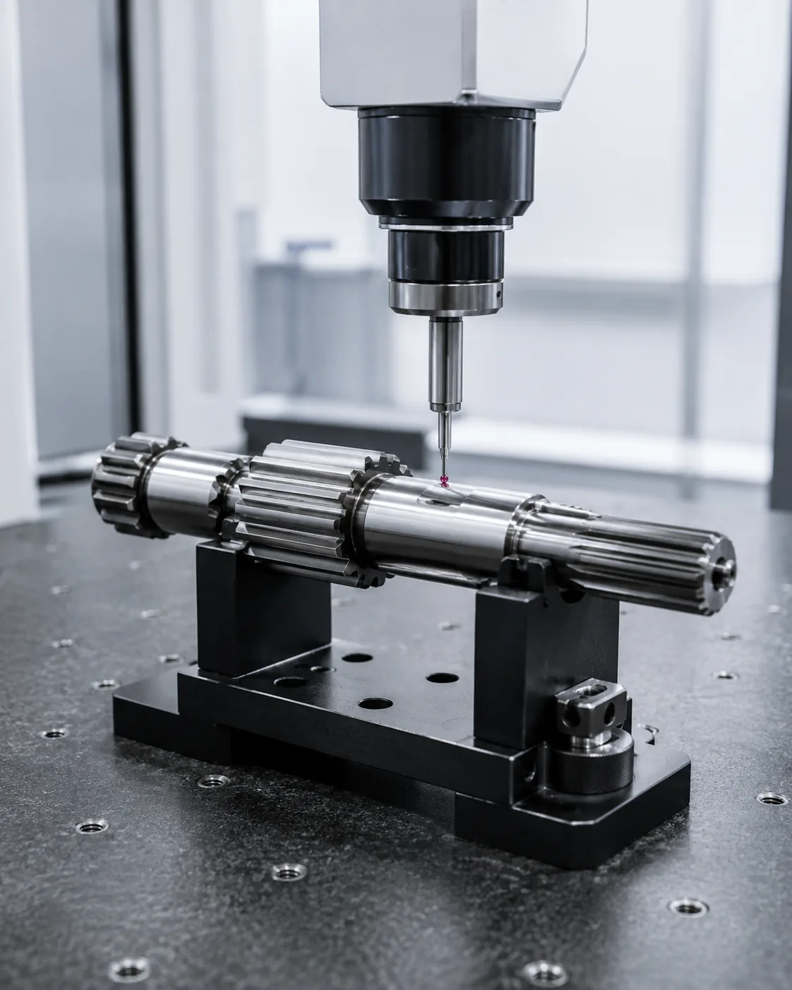
Tarkastuksen tulisi sidota kokoonpanoa ja vääntömomentin siirtoa ohjaaviin ominaisuuksiin. Piirustuksesta riippuen tämä voi sisältää toiminnallisen uramittauksen, analyyttisen hammasmittauksen, koordinaattimittauskoneella tehtävät tarkastukset, mittauksen tappien tai kuulien yli soveltuvin osin, heittotarkastus, pinnankarheuden mittaus ja kovuusmittaus. Mittausmenetelmän tulee vastata toleranssimääritelmää, jotta toimittaja ja asiakas arvioivat saman ominaisuuden samalla tavalla.
Lämpökäsitellyillä akseleilla on määritettävä kovuuden sijainti ja se, koskeeko vaatimus vain pinnan kovuutta vai myös kotelon syvyyttä ja sydämen kuntoa. Integroitujen hammaspyörä- ja uraosien osalta on suunniteltava hammasjärjestelmien ja laakeritappien välisen suhteen tarkastus sen sijaan, että tarkastettaisiin kutakin ominaisuutta erikseen. Ensimmäisen artikkelin raporttien tulisi keskittyä kriittisiin piirustusominaisuuksiin, jotka osoittavat sopivuuden ja toiminnallisen linjauksen.
Mukauttamisen ja piirtämisen tarkistuslista
Ever-Power voi arvioida räätälöityä geometriaa kontrolloidusta piirustuksesta tai mitoitetusta rajapintamääritelmästä. Tarjouksen laatimiseksi liitä mukaan alla olevat kokoonpanoosi soveltuvat tiedot:
- 2D-piirustus revisiotasoineen, datumeineen ja täydellisene spline-määrittelyineen
- Napa-, holkki-, hammaspyörä- tai haarukkageometria ja vaadittava kiinteä tai liukuva sovitus
- Materiaalilaatu, lämpökäsittelyolosuhteet, kovuus ja toiminnalliset pintakäsittelyvaatimukset
- Vääntömomentti, nopeus, isku- tai peruutuskuormitus, käyttösuhde, voitelu ja käyttöympäristö
- Kriittisen heiton, samankeskisyyden, aksiaalisen sijainnin ja laakeri- tai tiivisterajapinnan vaatimukset
- Tilausmäärä, prototyypin tai ensimmäisen artikkelin vaatimus ja pyydetyt tarkastusasiakirjat
Vahvista tälle kokoonpanolle myös: Hammaspyörän painekulma; hammaspyörän painekulma; hammaspyörän muoto; hammaspyörän sovitus; teholliset pituudet; laakeritapit; peruspiste- ja heittovaatimukset; vääntömomentti ja nopeus; sovelluspiirustus.
Vertaile toisiinsa liittyviä vaihtoehtoja Vaihde- ja ura-akselit alue tai käytä ura-akselin piirustusten tarkistuslista ennen tarjouspyynnön lähettämistä.
Asennus-, huolto- ja vikaantumisriskien tarkastukset
Ennen kokoamista varmista, että molemmat liitososat ovat puhtaat, vahingoittumattomat ja mitoiltaan yhteensopivia. Älä väkisin purista uraliitosta, joka puristuu kiinnityksen aikana; tutki purseet, linjaus, sovitus ja eteneminen ennen kokoonpanovoiman kohdistamista. Jos voitelua tarvitaan, käytä koneelle tai voimansiirrolle määritettyä voiteluainetta ja huoltovälejä sen sijaan, että valitsisit voiteluaineen pelkästään akselimateriaalin perusteella.
Huollon aikana tarkista akseli kitkajäljet, syöpymiset, epänormaali reunan kiillotus, korroosio, löysyys ja välyksen muutokset. Nämä oireet voivat johtua akselista, vastakappaleesta, tukilaakereista tai kokoonpanon linjauksesta. Vain näkyvästi kuluneen osan vaihtaminen ilman vastaliitoksen tarkistamista voi johtaa saman vikamekanismin jatkumiseen.
Suunnittelukatselmuksen muistiinpanot toistettavaa tuotantoa varten
Toistettavuus riippuu muustakin kuin nimellisestä uramitasta. Pidä piirustusten, liitoskomponenttien, viitejärjestelmän ja sovitun tarkastusmenetelmän kokoonpano hallinnassa. Jos liitosnapa, laakerijärjestely, lämpökäsittely tai käyttötarkoitus muuttuu, tarkista liitoskohta uudelleen, koska fyysisesti sopiva akseli ei välttämättä säilytä samaa kosketuskuviota, välystä tai kuorman jakautumista.
Kun yhdelle akselille valmistetaan useita ominaisuuksia, toleranssien kohdentamisen tulisi seurata toimintoa. Laakeripesät normaalisti ohjaavat pyörimistä, olakkeet aksiaalista sijaintia ja ura- tai hammaspyöräominaisuudet siirtävät vääntömomenttia. Piirustuksen tulisi tehdä nämä suhteet näkyviksi, jotta valmistussuunnitelmassa voidaan käyttää vakaita viitearvoja ja tarkastussuunnitelmassa voidaan toistaa kokoonpanologiikka. Tämä on erityisen tärkeää lämpökäsittelyn jälkeen, kun suoruus tai ominaisuuksien suhde voi muuttua ja valitut pinnat voivat vaatia lopullista viimeistelyä.
Hankinnassa vältä määrittelemästä prosessitietoja, jotka eivät suojaa toiminnallista vaatimusta. Toimittaja voi valita erilaisia työkalu- tai konejärjestyksiä ja silti saavuttaa saman valmiin geometrian. Keskity tarjouspyynnössä mitattavissa oleviin hyväksymiskriteereihin: materiaali, lämpökäsittely, kovuus, hammasgeometria, sovite, heitto, pinnanlaatu, mitat ja vaaditut raportit. Tämä pitää tarjoukset vertailukelpoisina ja mahdollistaa samalla tehokkaan prosessireitin.
Tuotantopiirustusten vaatimukset
Tuotantoa varten määrittele koko liitospinta pelkän nimellisen uran koon sijaan. Piirustuksessa tulee näkyä hammasjärjestelmä, tehokas kosketus, kokonaispituus, vierekkäiset akselitapit ja olakkeet, viitepisteet, vaadittu heitto, materiaalin kunto ja mahdollinen toiminnallinen pinnan viimeistely. Jos osan on korvattava olemassa oleva akseli, määritä, mitkä mitat on mitattu kulumattomista osista, ja anna liitosnavan, holkin, haarukan tai hammaspyörän tiedot, jos ne ovat saatavilla.
Ilmoita myös käyttötiedot, jotka vaikuttavat tekniseen tarkasteluun: välitetty vääntömomentti, pyörimisnopeus, suunnanvaihto tai iskukuormitus, voitelu, likaantuminen, lämpötila, aksiaalinen liike ja odotettu kokoonpanomenetelmä. Nämä tiedot auttavat yhdenmukaistamaan valmistus- ja tarkastussuunnitelman todellisen liitoksen kanssa. Kriittiset tarkastusominaisuudet tulisi tunnistaa piirustuksesta, jotta samaa hyväksymisperustetta voidaan käyttää sekä ensimmäisille artikkeleille että toistuville tilauksille.
Usein kysytyt kysymykset
Nämä kysymykset kattavat tiedot, joita useimmiten tarvitaan ura-akselikyselyn muuttamiseksi valmistettavaksi ja tarkastettavaksi piirustukseksi.
Mitä tietoja tarvitaan ennen kuin tästä ura-akselista voidaan antaa hinta-arvio?
Lähetä tarkastettu piirustus, määrä, liitosurien tiedot, materiaali- ja lämpökäsittelyvaatimukset, vääntömomentti ja nopeus, käyttöympäristö sekä tarvitsemasi tarkastuspöytäkirjat. Jos piirustus on puutteellinen, yksilöi avoimet mitat, jotta ne voidaan ratkaista teknisessä tarkastuksessa ennen tuotantoa.
Voiko spline-geometriaa mukauttaa?
Kyllä, räätälöity moduuli tai jako, hammasluku, puristuskulma, halkaisijat, kytkeytyminen ja vierekkäiset akselin ominaisuudet voidaan arvioida liitoskohdasta ja käyttötarkoituksesta. Kaikki hammasgeometrian muutokset on tarkistettava liitoselementtiä vasten, koska ne muuttavat sovitusta, kosketusta ja vaihdettavuutta.
Miten kovuus tulisi määrittää?
Ilmoita kovuusarvo yhdessä mittauspaikan kanssa ja tarvittaessa pintakarkaisusyvyyden tai ydinosan vaatimusten kanssa. Yksittäinen kovuusluku ei automaattisesti määrittele koko akselin kuntoa, varsinkaan käytettäessä paikallisia tai pintakarkaisuprosesseja.
Miten vuotoa tulisi hallita?
Sido heitto toiminnalliseen tietopisteeseen, kuten laakeritappiin, ohjaushalkaisijaan tai hammaspyörän referenssiin. Toleranssin tulisi suojata kokoonpanoa ja kosketusta sen sijaan, että se olisi vain mahdollisimman tiukka. Näytä tietopiste ja mittausolosuhteet piirustuksessa.
Mitä kulunutta akselia vaihdettaessa tulisi tarkistaa?
Tarkasta vastanapa tai -holkki sekä akseli. Mittaa kulumattomat alueet mahdollisuuksien mukaan ja dokumentoi hankautumis-, kuoppautumis-, epäsymmetrisen kosketuksen tai löysyyden esiintyminen. Nämä havainnot auttavat erottamaan normaalin kulumisen sopivuus-, linjaus- tai voiteluongelmista.
Pyydä tarjous
- Hallittu piirustus ja tarkistus
- Liitosurien/rajapintojen tiedot
- Materiaali- ja lämpökäsittelyvaatimukset
- Käyttötehtävät ja ympäristö
- Määrä- ja tarkastusdokumentaatio
Lähetä piirustukset ja sovelluksen tiedot alla olevan kyselylomakkeen kautta. Tekninen tarkastelu keskittyy liitoskohtaan, materiaalin kuntoon, toiminnallisiin tietoihin, käyttötehtävään ja tarkastusvaatimuksiin, joten tarjous perustuu todelliseen komponenttimääritelmään.
Pyydä tekninen tarjous
Lähetä piirustus, vastakappale, materiaalin kunto, määrä, vääntömomentti-/nopeustiedot ja tarkastusvaatimukset.