Hoe verkeerde uitlijning de vertanding en de bijbehorende naven beschadigt. — Een verkeerde uitlijning concentreert de belasting op de tandranden in plaats van het contact te verdelen over de beoogde flank. Lagerpositie, slingering, asbuiging, montagekrachten en onnauwkeurige referentiepunten kunnen hier allemaal aan bijdragen, dus corrigerende maatregelen moeten betrekking hebben op het complete positioneringssysteem.
Voor verkeerde uitlijning van de spie-asDe meest betrouwbare specificatie is er een die door een ontwerper, koper, fabrikant en inspecteur allemaal op dezelfde manier kan worden geïnterpreteerd. De onderstaande discussie richt zich op meetbare gegevens uit tekeningen, montageomstandigheden en praktische controles, in plaats van universele claims over koppel, pasvorm of levensduur die niet kunnen worden vastgesteld zonder volledige geometrie- en gebruiksgegevens.
Randbelasting op splineflanken
Randbelasting op splineflanken Dit moet worden beoordeeld in de context van uitlijningsfouten van de spiebaan. Identificeer het bijbehorende onderdeel, de werkingsfunctie en het tekeningkenmerk waarop deze beslissing betrekking heeft. De eis moet meetbaar zijn en verband houden met passing, koppeloverdracht, uitlijning, slijtage of een andere gedefinieerde montagebehoefte.
Houd bij de beslissing rekening met de materiaaltoestand, de productievolgorde en de inspectiemogelijkheden. Als het om een vervangingsonderdeel gaat, vergelijk dan de ongesleten geometrie met het bijbehorende onderdeel in plaats van de beschadiging te kopiëren. Houd bij nieuwe ontwerpen de proceskeuzes flexibel, tenzij een specifiek proces door het ontwerp zelf vereist is. Koppel deze beslissing in dit geval aan het bijbehorende onderdeel en de tekeningrevisie die voor de offerteaanvraag is gebruikt. Wanneer de uitlijningsafwijking van de spline-as verandert, moet dit punt opnieuw worden bekeken.
Verbuiging door verkeerde uitlijning van het lager
Verbuiging door verkeerde uitlijning van het lager Bepaalt hoe de spiebaan zich bevindt ten opzichte van de onderdelen die de rotatie mogelijk maken. Functionele referentiepunten worden doorgaans gekozen uit lagertappen, centreerdiameters, schouders of andere oppervlakken die het onderdeel in de assemblage positioneren. De tolerantie moet deze relatie tijdens de inspectie reproduceren.
Vermijd het gebruik van geometrische toleranties als geïsoleerde kwaliteitsindicatoren. Bepaal welke uitlijningsafwijking de assemblage kan tolereren, identificeer het referentiekader en specificeer het te controleren kenmerk. Warmtebehandeling en de uiteindelijke afwerking kunnen de relatie veranderen, dus de meting moet worden uitgevoerd in de productiefase die representatief is voor het afgewerkte onderdeel. In deze beoordeling is het bruikbare acceptatiecriterium er een dat kan worden herleid tot een functioneel kenmerk op de tekening. Voor de controle 'Hoe uitlijningsafwijkingen schade toebrengen aan spievertandingen en bijbehorende naven', past u deze controle toe op de specifieke uitlijningsafwijking van de spie-as die op de huidige tekening is weergegeven.
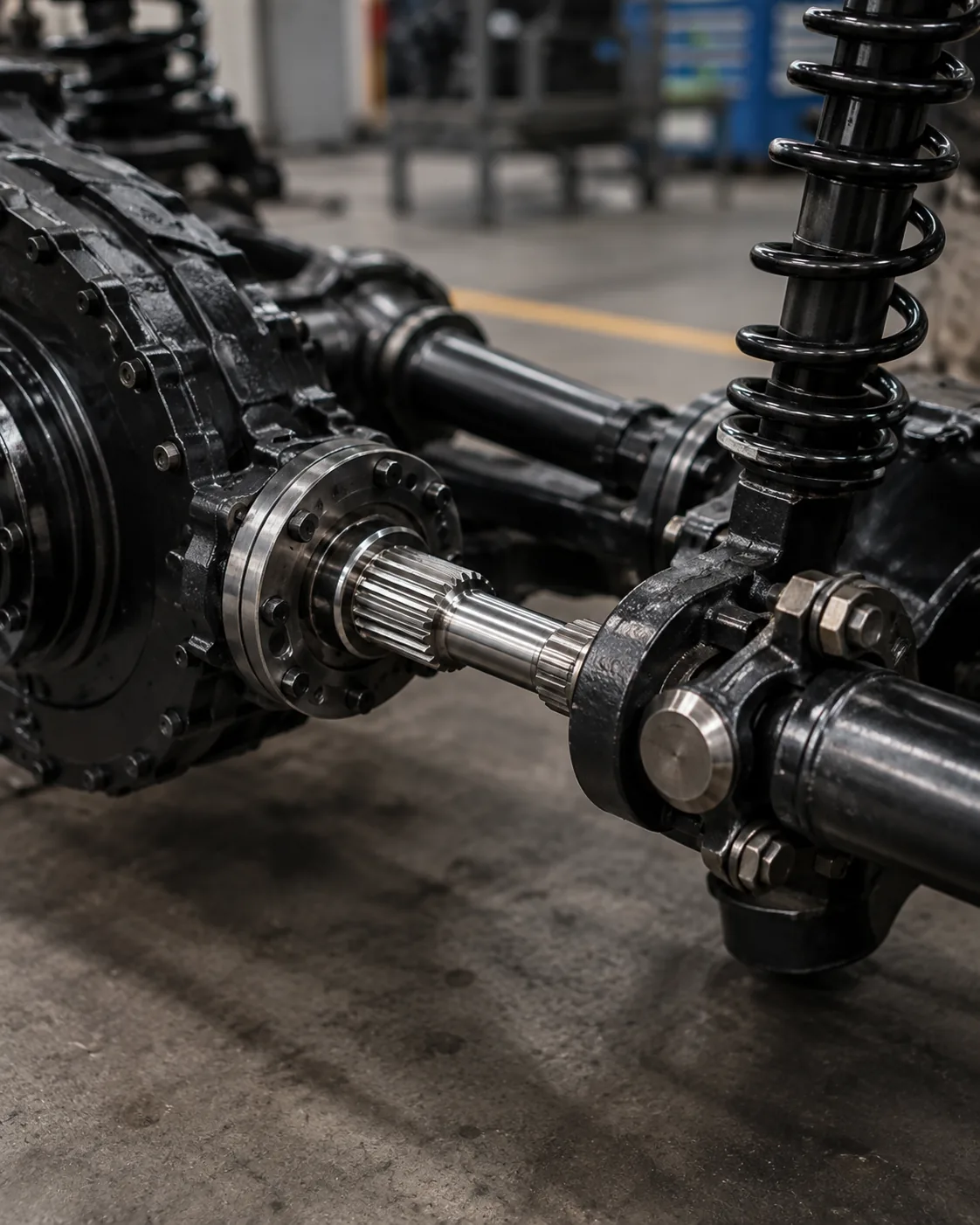
Uitloop- en datumfouten
Uitloop- en datumfouten Bepaalt hoe de spiebaan zich bevindt ten opzichte van de onderdelen die de rotatie mogelijk maken. Functionele referentiepunten worden doorgaans gekozen uit lagertappen, centreerdiameters, schouders of andere oppervlakken die het onderdeel in de assemblage positioneren. De tolerantie moet deze relatie tijdens de inspectie reproduceren.
Vermijd het gebruik van geometrische toleranties als geïsoleerde kwaliteitsindicatoren. Bepaal welke uitlijningsafwijking de assemblage kan tolereren, identificeer het referentiekader en specificeer het te controleren kenmerk. Warmtebehandeling en de uiteindelijke afwerking kunnen de verhouding veranderen, dus de meting moet worden uitgevoerd in de productiefase die het afgewerkte onderdeel vertegenwoordigt. Houd voor herhaalopdrachten hetzelfde referentiekader en dezelfde meetbasis aan, tenzij de eisen aan de assemblage veranderen. Voor de vraag hoe uitlijningsafwijkingen spievertandingen en bijbehorende naven beschadigen, dient u de resulterende eis vast te leggen op de tekening of in de inkoopspecificatie, zodat deze consistent blijft bij herhaalopdrachten.
Assembleeafdwinging
Assembleeafdwinging Dit plaatst de spiebaan in een operationele context. Koppelrichting, schokbelasting, vervuiling, smering, axiale beweging, lagerondersteuning en toegang voor onderhoud kunnen allemaal van invloed zijn op wat praktisch haalbaar is qua passing en materiaalconditie.
Beschrijf bij een offerteaanvraag de daadwerkelijke functie van de machine of assemblage en geef het bijbehorende onderdeel aan. Verzoeken om vervanging moeten foto's van slijtageplekken en metingen van niet-versleten delen bevatten. Deze informatie helpt geometrische problemen te onderscheiden van uitlijnings-, smeer- of onderhoudsproblemen elders in het systeem. Wanneer de toepassing of het bijbehorende onderdeel verandert, moet dit punt opnieuw worden bekeken in plaats van uit te gaan van de vorige aanname.
Ongelijkmatige slijtagepatronen
Ongelijkmatige slijtagepatronen Dit moet worden onderzocht als een symptoom van een defecte verbinding. Noteer waar de schade optreedt, of deze symmetrisch is, de toestand van het tegenoverliggende onderdeel, de smeerhistorie en eventuele speling of uitlijningsproblemen voordat de onderdelen worden gereinigd of weggegooid.
De corrigerende maatregelen zijn afhankelijk van het mechanisme. Een hardere vervangende as zal een excentrische naaf, onvoldoende vertanding of vervuilde smeerolie niet verhelpen. Vergelijk beide onderdelen, controleer de steunlagers en referentiepunten en verifieer de beoogde passing voordat u materiaal of tolerantie wijzigt. Koppel deze beslissing in dit geval aan het tegenstuk en de tekeningrevisie die voor de offerteaanvraag is gebruikt. Bij een offerteaanvraag voor een uitlijnfout van een spline-as, moet dit punt gekoppeld worden aan het tegenstuk, het referentiepuntenschema en de acceptatiemethode voor het eindproduct.
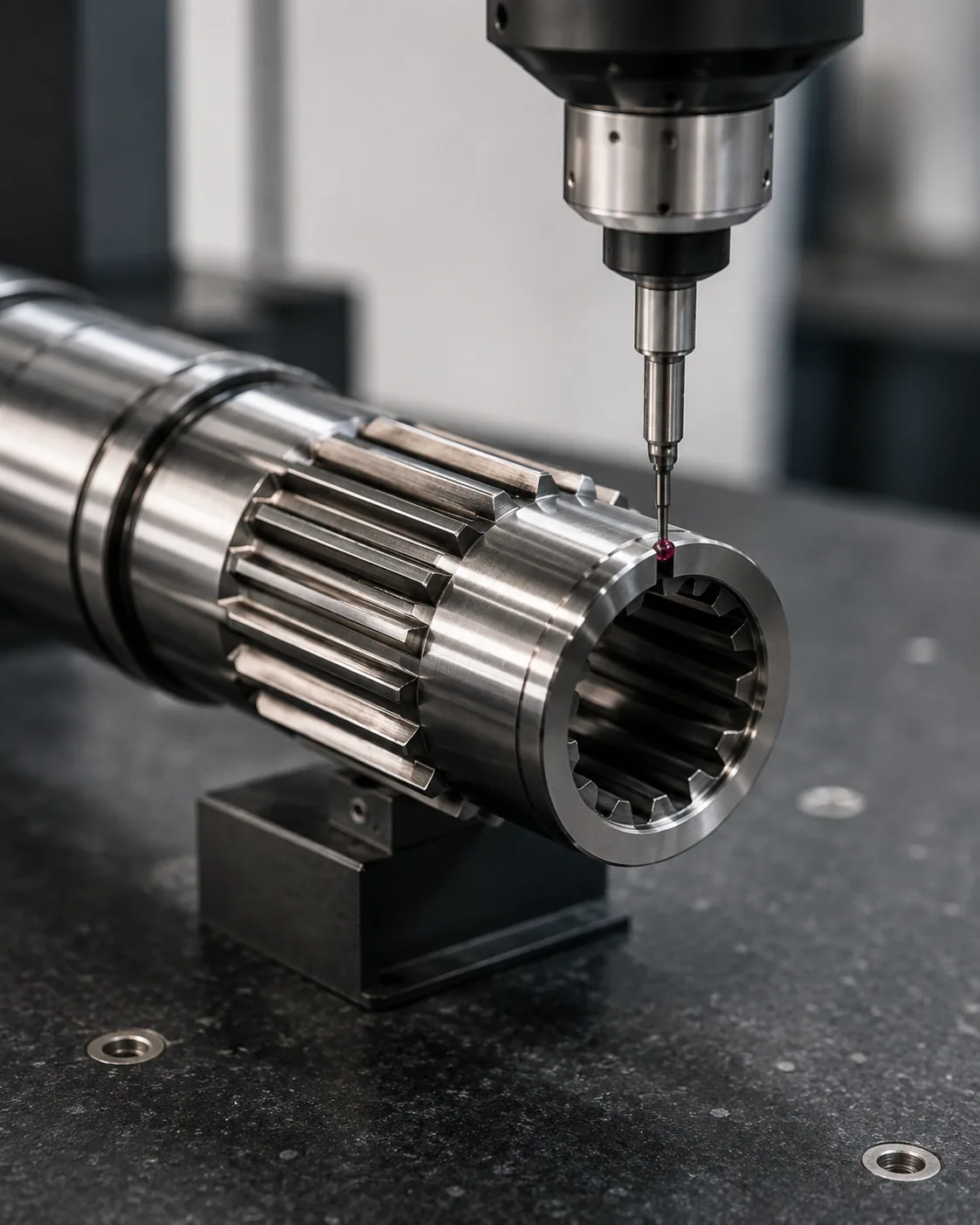
Fretting en Pitting
Fretting en Pitting Dit moet worden onderzocht als een symptoom van een defecte verbinding. Noteer waar de schade optreedt, of deze symmetrisch is, de toestand van het tegenoverliggende onderdeel, de smeerhistorie en eventuele speling of uitlijningsproblemen voordat de onderdelen worden gereinigd of weggegooid.
Corrigerende maatregelen zijn afhankelijk van het mechanisme. Een hardere vervangingsas zal een excentrische naaf, onvoldoende vertanding of vervuild smeermiddel niet verhelpen. Vergelijk beide onderdelen, controleer de steunlagers en referentiepunten en verifieer de beoogde passing voordat u materiaal of tolerantie wijzigt. In deze beoordeling is het bruikbare acceptatiecriterium er een dat kan worden herleid tot een functioneel tekeningkenmerk. Voor de vraag hoe verkeerde uitlijning spievertandingen en bijbehorende naven beschadigt, dient u de resulterende eis vast te leggen op de tekening of in de inkoopspecificatie, zodat deze consistent blijft bij herhaalbestellingen.
Een praktische herhalingsreeks
Een praktische controleprocedure begint met het aansluitende onderdeel en het koppelpad, waarna het tandsysteem, de vertanding en de aseigenschappen die de verbinding positioneren, worden gecontroleerd. Vervolgens worden het materiaal en de warmtebehandeling, de functionele afwerkingen en eventuele slingering- of positioneringsvereisten vastgelegd. Voor herhaalopdrachten dient dezelfde referentie en meetbasis te worden aangehouden, tenzij de montagevereisten wijzigen. Voor de vraag hoe verkeerde uitlijning spievertandingen en bijbehorende naven beschadigt, dient de resulterende vereiste op de tekening of inkoopspecificatie te worden vastgelegd, zodat deze consistent blijft bij herhaalopdrachten.
Sluit af met het overeenkomen van de inspectiemethode, de hoeveelheid en de documentatie van het eerste exemplaar. Deze volgorde voorkomt dat proces- of tolerantiebeslissingen worden genomen voordat de functionele interface duidelijk is en maakt offertes gemakkelijker te vergelijken, omdat dezelfde ontwerpgegevens aan elke leverancier worden gepresenteerd. Wanneer de functie of het aansluitende onderdeel verandert, moet dit punt opnieuw worden bekeken in plaats van de vorige aanname te hanteren. Voor de vraag hoe verkeerde uitlijning spievertandingen en aansluitende naven beschadigt, moet de resulterende eis worden vastgelegd op de tekening of inkoopspecificatie, zodat deze consistent blijft bij herhaalbestellingen.
Inspectie van beide aansluitende onderdelen
Inspectie van beide aansluitende onderdelen Dit beïnvloedt het contactoppervlak, het montagegevoel en de lastverdeling. Effectief contact is de lengte waarover de tandflanken daadwerkelijk een belasting kunnen dragen; afschuiningen, uitsparingen en onvolledige tandgedeelten mogen niet automatisch worden meegerekend als werkende lengte.
De passing moet worden beoordeeld als een paar op elkaar aansluitende onderdelen. Tanddikte, tussenruimte, diameterspeling, uitlijning en temperatuur spelen allemaal een rol. Inspecteer bij vervanging beide onderdelen, omdat slijtage in de naaf ervoor kan zorgen dat een nieuwe as los aanvoelt, zelfs als de nieuwe uitwendige vertanding binnen de toleranties van de tekening valt. Koppel deze beslissing in dit geval aan het aansluitende onderdeel en de tekeningrevisie die is gebruikt voor de offerteaanvraag. Voor het onderdeel 'Hoe verkeerde uitlijning vertanding en aansluitende naven beschadigt', dient u de resulterende eis vast te leggen op de tekening of in de inkoopspecificatie, zodat deze consistent blijft bij herhaalbestellingen.
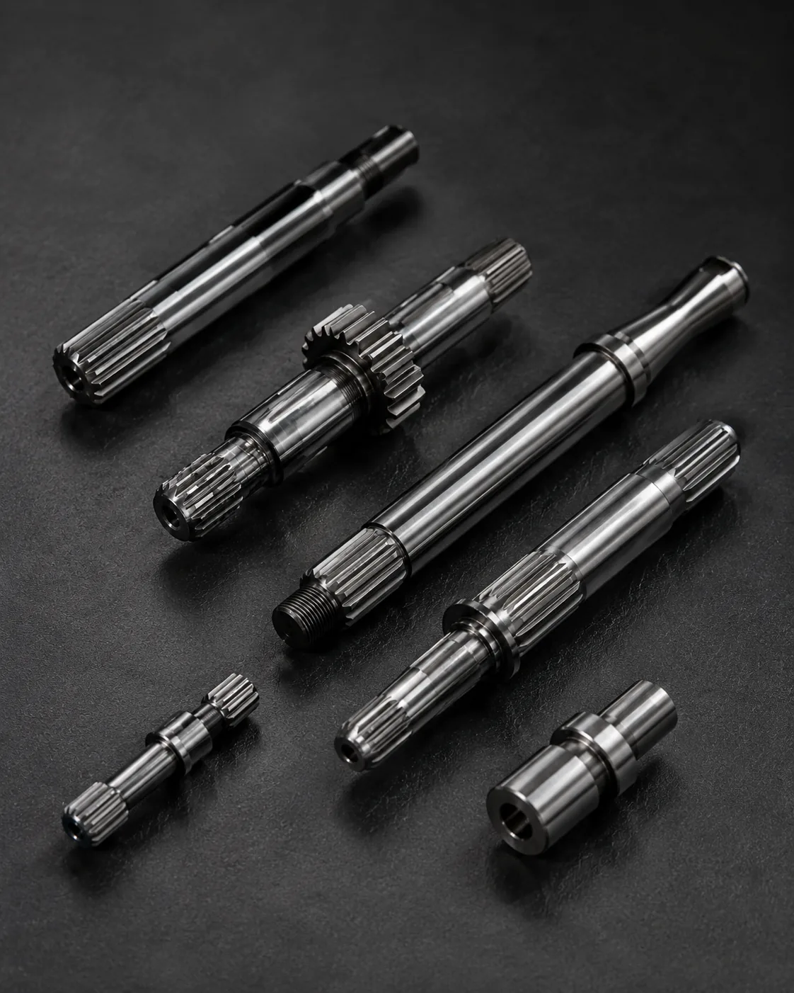
Corrigerende maatregelen vóórdat nieuwe onderdelen worden gebruikt
Corrigerende maatregelen vóórdat nieuwe onderdelen worden gebruikt Dit moet worden beoordeeld in de context van uitlijningsfouten van de spiebaan. Identificeer het bijbehorende onderdeel, de werkingsfunctie en het tekeningkenmerk waarop deze beslissing betrekking heeft. De eis moet meetbaar zijn en verband houden met passing, koppeloverdracht, uitlijning, slijtage of een andere gedefinieerde montagebehoefte.
Houd bij de beslissing rekening met de materiaaltoestand, de productievolgorde en de inspectiemogelijkheden. Als het om een vervangingsonderdeel gaat, vergelijk dan de ongesleten geometrie met het bijbehorende onderdeel in plaats van de beschadiging te kopiëren. Houd bij nieuwe ontwerpen de proceskeuzes flexibel, tenzij een specifiek proces door het ontwerp zelf vereist is. In deze beoordeling is het bruikbare acceptatiecriterium er een dat herleidbaar is tot een functioneel tekeningkenmerk. Voor de controle op de uitlijningsfout van de spievertanding en de bijbehorende naven, past u deze controle toe op de specifieke uitlijningsfout van de spie-as die op de huidige tekening is weergegeven.
Veelgemaakte fouten die je moet vermijden
Veelvoorkomende fouten bij het uitlijnen van spiebanen ontstaan doordat één nominale waarde wordt gebruikt alsof deze de volledige interface definieert. Ontbrekende drukhoek, onduidelijke referentiepunten, gekopieerde slijtagematen, een niet-gespecificeerde hardheidslocatie en niet-overeenkomende inspectiemethoden kunnen allemaal leiden tot onderdelen die er op papier correct uitzien, maar niet consistent gemonteerd kunnen worden.
Een betere beoordeling begint met het bijbehorende paar, identificeert het krachtenpad en de positioneringskenmerken, en koppelt vervolgens geometrie, materiaalconditie en inspectie aan die functies. Beantwoord openstaande vragen op de tekening vóór de productie en behoud de overeengekomen interpretatie bij de herziening voor herhaalopdrachten. Houd voor herhaalwerk dezelfde referentiepunten en meetbasis aan, tenzij de montage-eisen wijzigen. Voor de controle op schade aan spievertandingen en bijbehorende naven door verkeerde uitlijning, pas deze controle toe op de specifieke uitlijningsinterface van de spie-as die op de huidige tekening is weergegeven.
Samenvatting van de beslissing
| Beslissingsgebied | Wat te bevestigen | Waarom het belangrijk is |
|---|---|---|
| Koppelingsgeometrie | Tandsysteem, diameters, aangrijping en pasvorm | Besturingscompatibiliteit en flankcontact |
| Locatie | Referentiepunten, lagers, schouders en rondloop | Regelt de uitlijning in de assemblage. |
| Materiële toestand | Kwaliteit, warmtebehandeling, hardheid en afwerking | Definieert de afgewerkte mechanische en slijtagetoestand. |
| Plicht | Koppel, snelheid, schok, beweging en omgeving | Koppelt de onderdeeldefinitie aan de bedrijfsomstandigheden. |
| Inspectie | Gecontroleerde kenmerken en meetmethode | Zorgt voor consistente acceptatie tussen leverancier en koper. |
Specificatiechecklist
- Aansluitcomponent en externe/interne tandoriëntatie
- Module- of steeksysteem, aantal tanden, drukhoek en grote/kleine diameters
- Effectieve aansluiting, pasvorm of tolerantiebasis en axiale beweging indien vereist.
- Materiaal, warmtebehandeling, locatie van de hardheid en functionele oppervlakteafwerkingen
- Referentiepunten, lager- of pilotdiameters, slingering en axiale positioneringsvereisten
- Koppel, snelheid, schok- of omkeerbelasting, smering en bedrijfsomgeving
- Hoeveelheid, eisen voor het eerste exemplaar en overeengekomen inspectiedocumentatie
Gebruik de assortiment spie-assen om beschikbare configuraties te vergelijken en de RFQ-tekeningenchecklist Om een volledig onderzoek voor te bereiden. Wanneer de functie of het aansluitende onderdeel verandert, moet dit punt opnieuw worden bekeken in plaats van de vorige aanname te hanteren. Voor de controle op schade aan spievertandingen en bijbehorende naven door verkeerde uitlijning, moet deze controle worden toegepast op de specifieke interface voor verkeerde uitlijning van de spie-as die op de huidige tekening is weergegeven.
Technische werkblad voor uitlijningsfouten van spiebanen.
Gebruik dit werkblad om te draaien Hoe verkeerde uitlijning de vertanding en de bijbehorende naven beschadigt. in beslissingen die op een tekening kunnen worden weergegeven, tijdens de offertefase kunnen worden gecontroleerd en bij het eerste artikel kunnen worden geverifieerd. Begin met Randbelasting op splineflanken En Verbuiging door verkeerde uitlijning van het lager, omdat die twee elementen meestal ofwel de koppelingsgeometrie ofwel de materiaaltoestand bepalen waaraan de rest van het proces moet voldoen. Bekijk het vervolgens. Uitloop- en datumfouten, Assembleeafdwinging En Ongelijkmatige slijtagepatronen in plaats van ze te behandelen als onafhankelijke cataloguswaarden, en ze te vergelijken met de daadwerkelijke samenstelling.
Voor het oplossen van problemen is het belangrijk om de toestand te documenteren voordat de onderdelen worden gereinigd of weggegooid. Noteer de locatie van slijtage, vuil, polijsten, putjes, verkleuring, wrijving, contact tussen de tandranden en eventuele afwijkingen rond de omtrek. Controleer het tegenstuk, de conditie van het lager, het smeerpad en de uitlijning van de assemblage. Een vervanging die alleen gebaseerd is op de beschadigde as kan hetzelfde probleem veroorzaken als de onderliggende oorzaak elders in de verbinding ligt. Controleer dit punt opnieuw wanneer het tegenstuk, de materiaalconditie of de bedrijfsomstandigheden veranderen, om een verkeerde uitlijning van de spline-as te kunnen vaststellen.
Gebruik randbelasting op de flanken van de spiebanen, slingering en referentiefouten, en ongelijkmatige slijtagepatronen om het symptoom van de oorzaak te onderscheiden. Vergelijk metingen in niet-versleten gebieden, controleer referentiepunten en slingering, en zoek naar aanwijzingen voor onvoldoende aangrijping of ongelijkmatig contact tussen de flanken. Als de bedrijfsomstandigheden zijn gewijzigd, voeg dan het nieuwe koppel, de snelheid, de omkeerfrequentie, de temperatuur of de vervuilingsconditie toe aan de technische beoordeling voordat een vervangende tekening wordt vrijgegeven.
Tekenen beoordelingsvolgorde
Voordat u de productie aanvraagt, dient u de tekening in dezelfde volgorde te controleren als waarin de montage plaatsvindt: het tandwielsysteem, de effectieve vertanding, de referentiepunten, de aangrenzende lagers of schouders, het materiaal en de warmtebehandeling, de functionele afwerking en de inspectiemethode. verkeerde uitlijning van de spie-asDe volgorde is belangrijk omdat latere beslissingen, zoals de processelectie of de keuze van meetinstrumenten, de interface moeten ondersteunen in plaats van deze te herdefiniëren.
| Werkbladitem | Vraag om te beantwoorden | RFQ-output |
|---|---|---|
| Randbelasting op splineflanken | Welke assemblagefunctie wordt door deze functie aangestuurd? | Afmeting, tolerantie of koppelingsreferentie |
| Verbuiging door verkeerde uitlijning van het lager | Welke eindtoestand moet worden bereikt? | materiaal / warmtebehandeling / afwerking |
| Uitloop- en datumfouten | Hoe wordt de eigenschap geverifieerd? | Inspectiemethode of rapportagenotitie |
| Assembleeafdwinging | Hoe gaat de andere partij te werk? | Informatie over de paringsdelen en de betrokkenheid |
| Ongelijkmatige slijtagepatronen | Welke gegevens bepalen de functionele locatie? | Relatie tussen referentiepunt en uitloop |
Overdracht van inkoop vóór het eerste artikel
Een handig aankooppakket voor Hoe verkeerde uitlijning de vertanding en de bijbehorende naven beschadigt. De offerte bevat de gecontroleerde tekening, de hoeveelheid, het materiaal en de warmtebehandelingsconditie, informatie over de aansluitinterface en de acceptatiekenmerken die moeten worden gerapporteerd. Indien een 3D-model wordt aangeleverd, dient de 2D-tekening nog steeds toleranties, referentiepunten, aantekeningen over de warmtebehandeling en inspectie-eisen te bevatten. Vermeld de huidige revisie in de offerteaanvraag, zodat productie en inspectie niet met verschillende versies werken.
Wanneer een kenmerk nog niet vaststaat, markeer het dan voor technische verduidelijking in plaats van een gemakkelijke waarde in te voeren. Bij uitlijningsfouten van spiebanen zijn veelvoorkomende openstaande punten: inslag, passing, hardingslocatie, slingering ten opzichte van een aangrenzende as, toegankelijkheid van interne kenmerken of de staat van een versleten tegenstuk. Het oplossen van deze punten vóór de productie van het eerste exemplaar vermindert onnodig herstelwerk en maakt latere herhaalbestellingen gemakkelijker te controleren.
Checklist vóór de release
- Controleer de randbelasting op de flanken van de spline ten opzichte van het daadwerkelijke tegenstuk.
- Controleer in de afgewerkte toestand of er sprake is van doorbuiging als gevolg van een verkeerde uitlijning van de lagers.
- Definieer hoe afwijkingen in de slingering en datumfouten zullen worden gecontroleerd.
- Controleer de montagekracht onder de beoogde montageomstandigheden.
- Koppel ongelijkmatige slijtagepatronen aan de functionele referentiestructuur.
- Vermeld de hoeveelheid, het revisieniveau en eventuele documentatievereisten voor het eerste exemplaar.
- Noteer wijzigingen in gebruik, smering of bijbehorende onderdelen voor herhaalbestellingen.
Veelgestelde vragen
Wat moet ik controleren met betrekking tot de randbelasting op de flanken van de spiebaan bij een verkeerde uitlijning van de spiebaanas?
Koppel de randbelasting op de splineflanken eerst aan het tegenstuk en de assemblagefunctie. Plaats de meetbare eis op de gecontroleerde tekening en neem het tegenoverliggende onderdeel op wanneer de compatibiliteit van beide onderdelen afhangt. Voor het geval dat verkeerde uitlijning splinetanden en bijbehorende naven beschadigt, voorkomt dit dat een nominale aanduiding de geometrie vervangt die daadwerkelijk de passing en koppeloverdracht bepaalt.
Wat moet ik controleren met betrekking tot kromtrekking door verkeerde uitlijning van het lager bij verkeerde uitlijning van de spiebaanas?
Bevestig de buiging als gevolg van verkeerde uitlijning van de lagers in de afgewerkte toestand, inclusief alle materiaal-, warmtebehandelings-, oppervlakte- of dimensionale eigenschappen die na de bewerking kunnen veranderen. Als de eis afhankelijk is van een locatie of referentiepunt, geef dit dan expliciet aan, zodat productie en inspectie dezelfde referentie gebruiken.
Wat moet ik controleren met betrekking tot rondloop- en referentiepuntfouten bij verkeerde uitlijning van de spline-as?
Kies een inspectiemethode die de op de tekening genoemde eigenschap meet. Functionele metingen, analytische spline-metingen, CMM-controles, rondloopinspectie, ruwheidsmeting en hardheidstesten beantwoorden verschillende vragen. Geef aan welk resultaat vereist is voor acceptatie in plaats van een algemeen inspectierapport te vragen. Koppel dit punt in een offerteaanvraag voor uitlijningsfouten van een spline-as aan het bijbehorende onderdeel, het referentiepuntschema en de acceptatiemethode voor het eindproduct.
Wat moet ik controleren met betrekking tot de montagekracht bij een verkeerde uitlijning van de spie-as?
Controleer de montagekracht met het daadwerkelijke tegenstuk en de beoogde montageomstandigheden. Effectieve aangrijping, speling, axiale beweging, temperatuur en slijtage van een vervangende naaf kunnen allemaal van invloed zijn op het gedrag van de verbinding. Een nieuwe as mag niet alleen op gevoel worden goedgekeurd of afgekeurd wanneer er een meetbare passingseis beschikbaar is.
Wat moet ik controleren met betrekking tot ongelijkmatige slijtagepatronen bij een verkeerde uitlijning van de spiebaanas?
Koppel ongelijkmatige slijtagepatronen aan de kenmerken die de rotatie in de assemblage bepalen. De tekening moet het referentiepunt en eventuele slingering of positieverhoudingen duidelijk weergeven. Als warmtebehandeling of nabewerking het kenmerk kan verplaatsen, controleer dan de relatie in het stadium dat het afgewerkte onderdeel vertegenwoordigt.
Van technische beslissing tot productiecontrole
Zodra de interface is overeengekomen, vertaalt u elke functionele beslissing naar een tekeningkenmerk dat kan worden geproduceerd en geïnspecteerd. Vermijd het om belangrijke relaties alleen in e-mailnotities te vermelden. Afmetingen, referentiepunten, warmtebehandelingscondities en acceptatie-eisen moeten worden beheerd volgens versiebeheer, zodat het productieteam en het inspectieteam met dezelfde definitie werken. Voor herhaalopdrachten dient u dezelfde referentiepunten en meetbasis aan te houden, tenzij de montage-eisen wijzigen. Voor de vraag "Hoe uitlijningsfouten spievertandingen en bijbehorende naven beschadigen", dient u de resulterende eis vast te leggen op de tekening of inkoopspecificatie, zodat deze consistent blijft bij herhaalopdrachten.
Voor eerste artikelen dient u prioriteit te geven aan de kenmerken die de compatibiliteit van de montage aantonen: tandgeometrie, passing, relatie tot centreerpennen of -schouders, warmtebehandelingstoestand en eventuele kritische slingering. Noteer de meetmethode samen met het resultaat. Bij herhaalbestellingen maakt het gebruik van dezelfde referentie-instelling en meetmethode het gemakkelijker om trendveranderingen te herkennen en vermindert het geschillen die ontstaan door verschillende interpretaties van inspecties. Wanneer de functie of het aansluitende onderdeel verandert, dient u dit punt opnieuw te bekijken in plaats van de vorige aanname te hanteren. Voor de vraag hoe verkeerde uitlijning spievertandingen en aansluitende naven beschadigt, dient u de resulterende eis vast te leggen op de tekening of inkoopspecificatie, zodat deze consistent blijft bij herhaalbestellingen.
Wanneer de bedrijfsbelasting verandert, moet de technische beoordeling opnieuw worden uitgevoerd in plaats van ervan uit te gaan dat de oude specificatie nog steeds geschikt is. Een hoger koppel, grotere schokken, frequentere omkeringen, andere smering of een nieuw tegenstuk kunnen het contact en de slijtage veranderen, zelfs als de nominale spiebaanmaat hetzelfde blijft. De tekening moet meegroeien met de daadwerkelijke montage-eisen. Koppel deze beslissing voor dit onderwerp aan het tegenstuk en de tekeningrevisie die voor de offerteaanvraag is gebruikt. Voor de controle op schade aan spiebanen en bijbehorende naven door verkeerde uitlijning, moet deze worden toegepast op de specifieke interface voor verkeerde uitlijning van de spiebaanas die op de huidige tekening is weergegeven.
Bereid de offerteaanvraag voor
- Huidige 2D-tekening en revisie
- Definitie van het bijbehorende component en de spline
- Materiaal, warmtebehandeling en functionele afwerkingen
- Koppel, snelheid, belasting en omgeving
- Hoeveelheid en vereiste inspectiedocumentatie
Een complete offerteaanvraag combineert de tekening, de aansluiting, de materiaaleigenschappen, de toepassing, de hoeveelheid en de inspectie-eisen. Wanneer deze input vroegtijdig wordt vastgelegd, kunnen leveranciers de matrijs, warmtebehandeling, afwerking en meting plannen op basis van dezelfde functionele eis, waardoor het aantal verduidelijkingscycli vóór de eerste prototypeproductie wordt verminderd. In deze beoordeling is het bruikbare acceptatiecriterium er een dat kan worden herleid tot een functioneel kenmerk van de tekening. Bij een offerteaanvraag voor een uitlijningsfout van een spline-as, moet dit punt gekoppeld worden aan het aansluitende onderdeel, het referentieschema en de acceptatiemethode voor het eindproduct.
Zet de handleiding om in een offerteaanvraag (RFQ).
Stuur de gecontroleerde tekening, de koppelingsinterface, de materiaaleigenschappen en de gegevens over de belasting ter technische beoordeling.
Vraag een offerte aan