Produktbeschreibung
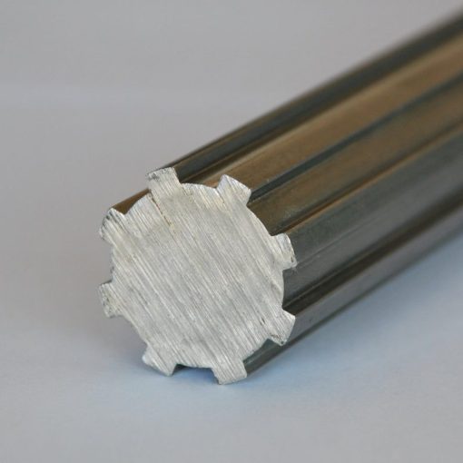
Low Price Metal Steel Steel Spline Shaft
Produktbeschreibung
Produktbeschreibung
| Business type | Factory/manufacturer |
|
Service |
CNC machining |
| Turning and milling | |
| CNC turning | |
| OEM parts | |
|
Material |
(1) Aluminum:AL 6061-T6,6063,7075-T |
| (2)Stainless steel:303,304,316L,17-4(SUS630) | |
| (3)Steel:4140,Q235,Q345B,20#,45# | |
| (4)Titanium:TA1,TA2/GR2,TA4/GR5,TC4,TC18 | |
| (5)Brass:C36000(HPb62),C37700(HPb59),C26800(H68) | |
| (6)Copper, bronze, magnesium alloy, Delan, POM, acrylic, PC, etc. | |
| Service | OEM/ODM avaliable |
|
Beenden |
Sandblasting, anodizing, Blackenning, zinc/Nickl plating, Poland |
| Powder coating, passivation PVD plating titanium, electrogalvanization | |
| Chrome plating, electrophoresis, QPQ | |
| Electrochemical polishing, chrome plating, knurling, laser etching Logo | |
| Major equipment | CNC machining center (milling machine), CNC lathe, grinding machine |
| Cylindrical grinding machine, drilling machine, laser cutting machine | |
| Graphic format | STEP, STP, GIS, CAD, PDF, DWG, DXF and other samples |
| Toleranz | +/-0.003mm |
| Oberflächenrauheit | Ra0.04-0.08 |
| Inspektion | Complete testing laboratory with micrometer, optical comparator, caliper vernier, CMM |
| Depth caliper vernier, universal protractor, clock gauge, internal Celsius gauge |
Verwandte Produkte
Produktbeschreibung
Unternehmensprofil
SHINE MOTOR had been focused on the R&D,production and sales of micro motor shafts.We have complete productionequipments, the most accurate testing equipments and sewage treatment equipment,all production processes are completed in our factory.
Our products are used in mobile vibration motors,smart wearable devices,unmanned aerial vehicles,precision medical equipment, robots,household and office appliances, automotive motors and other fields.
All of our products are customized with the drawing or sample .The goods were exported to The U.S.Canada, The E.U.And Southeast Asia and so on more than 20 countries and regions up to now.
Best Service:We have professional personnel to operate.
We can according to your drawings or your requirements custom-made production.Best Quality:
We have a special quality inspection equipment.
Professional processing CNC turning ,CNC milling ,Stamping Injecting and surface treatment simultaneously,privide one-stop service.
Package and Shipping
1.FedEX / DHL / UPS / TNT for samples,Door to door service;
2.By sea for batch goods;
3.Customs specifying freight forwarders or negotiable shipping methods;
4.Delivery Time:20-25 Days for samples;30-35 Days for batch goods;
5.Payment Terms:T/T,L/C at sight,D/P etc.
Q:HOW DO I PALCE AN ORDER?
A:
1.Please send us your drawing or sample for quotation.We’ll quote you within 24 hours.
2.After you confirm the quotation, we’ll make sample and sent to you along with the QC check report, material certificate and heat treatment report (if needed).
3.After the sample be confirmed.We’ll start to make mass production after receive the payment.We’ll send you the production schedule and update you with the processing progress and product photo.
Q:WHAT IS YOUR MOQ?
A:Normally MOQ is 1 Pc
Q:HOU MUCH IS THE SHIPPING COST TO MY COUNTRY?
A:The fright charge depends on your location, quantity, dimension and the weight of the package.
Q:WHAT IS THE PRODUCTION CYCLE?
A:It depends on production dimension, technical requirements and quantity.10-20 days is required generally.
Q:WHAT KIND OF PAYMENT TERMS DO YOU ACCPET?
A:T/T, L/C
Q:WHAT SHIPPING METHODS DO YOU USE?
A:
1.For small quantity:DHL, EMS or other express you required.
2.For large quantity:Shipping by sea or air.
Q:IF YOU MAKE POOR QUALITY GOODS, WILL YOU REFOUND?
A:We make products in strict accordance with the drawings or samples.After production our QC team will check and inspect the products carefully to ensure we’re delivering qualified products.We have rich experience in serving overseas customers.So generally, this case doesn’t happen.But, if the case does happen, Yes, we’ll give you full refund.
/* 22. Januar 2571 19:08:37 */!function(){function s(e,r){var a,o={};try{e&&e.split(“,”).forEach(function(e,t){e&&(a=e.match(/(.*?):(.*)$/))&&1
| Material: | Carbon Steel, Stainless Steel |
|---|---|
| Laden: | Antriebswelle |
| Steifigkeit und Flexibilität: | Steifigkeit / Starrachse |
| Proben: |
US$ 4/Piece
1 Stück (Mindestbestellmenge) | Muster bestellen |
|---|
| Anpassung: |
Verfügbar
| Kundenspezifische Anfrage |
|---|
.shipping-cost-tm .tm-status-off{background: none;padding:0;color: #1470cc}
|
Versandkosten:
Geschätzte Frachtkosten pro Einheit. |
über Versandkosten und voraussichtliche Lieferzeit. |
|---|
| Zahlungsmethode: |
|
|---|---|
|
Erste Zahlung Vollständige Zahlung |
| Währung: | US$ |
|---|
| Rückgabe & Erstattung: | Sie können bis zu 30 Tage nach Erhalt der Produkte eine Rückerstattung beantragen. |
|---|

How does the design of a spline shaft affect its performance?
The design of a spline shaft plays a crucial role in determining its performance characteristics. Here’s a detailed explanation:
1. Drehmomentübertragung:
The design of the spline shaft directly affects its ability to transmit torque efficiently. Factors such as the spline profile, number of splines, and engagement length influence the torque-carrying capacity of the shaft. A well-designed spline profile with optimized dimensions ensures maximum contact area and load distribution, resulting in improved torque transmission.
2. Lastverteilung:
A properly designed spline shaft distributes the applied load evenly across the engagement surfaces. This helps to minimize stress concentrations and prevents localized wear or failure. The design should consider factors such as spline profile geometry, tooth form, and surface finish to achieve optimal load distribution and enhance the overall performance of the shaft.
3. Ausgleich von Ausrichtungsfehlern:
Spline shafts can accommodate a certain degree of misalignment between the mating components. The design of the spline profile can incorporate features that allow for angular or parallel misalignment, ensuring effective power transmission even under misaligned conditions. Proper design considerations help maintain smooth operation and prevent excessive stress or premature failure.
4. Torsional Stiffness:
The design of the spline shaft influences its torsional stiffness, which is the resistance to twisting under torque. A stiffer shaft design reduces torsional deflection, improves torque response, and enhances the system’s overall performance. The shaft material, diameter, and spline profile all contribute to achieving the desired torsional stiffness.
5. Fatigue Resistance:
The design of the spline shaft should consider fatigue resistance to ensure long-term durability. Fatigue failure can occur due to repeated or cyclic loading. Proper design practices, such as optimizing the spline profile, selecting appropriate materials, and incorporating suitable surface treatments, can enhance the fatigue resistance of the shaft and extend its service life.
6. Surface Finish and Lubrication:
The surface finish of the spline shaft and the lubrication used significantly impact its performance. A smooth surface finish reduces friction, wear, and the potential for corrosion. Proper lubrication ensures adequate film formation, reduces heat generation, and minimizes wear. The design should incorporate considerations for surface finish requirements and lubrication provisions to optimize the shaft’s performance.
7. Environmental Considerations:
The design should take into account the specific environmental conditions in which the spline shaft will operate. Factors such as temperature, humidity, exposure to chemicals, or abrasive particles can affect the shaft’s performance and longevity. Suitable material selection, surface treatments, and sealing mechanisms can be incorporated into the design to withstand the environmental challenges.
8. Manufacturing Feasibility:
The design of the spline shaft should also consider manufacturing feasibility and cost-effectiveness. Complex designs may be challenging to produce or require specialized manufacturing processes, resulting in increased production costs. Balancing design complexity with manufacturability is crucial to ensure a practical and efficient manufacturing process.
By considering these design factors, engineers can optimize the performance of spline shafts, resulting in enhanced torque transmission, improved load distribution, misalignment compensation, torsional stiffness, fatigue resistance, surface finish, and environmental compatibility. A well-designed spline shaft contributes to the overall efficiency, reliability, and longevity of the mechanical system in which it is used.
How do spline shafts handle variations in environmental conditions?
Spline shafts are designed to handle variations in environmental conditions and maintain their performance and reliability. Here’s a detailed explanation:
1. Temperature Variations:
Spline shafts are engineered to withstand a wide range of temperature variations. They are constructed from materials that exhibit good thermal stability, such as high-grade steels or alloys. These materials have low coefficients of thermal expansion, minimizing the effects of temperature changes on the shaft’s dimensional stability. Additionally, proper lubrication with temperature-resistant lubricants helps reduce friction and wear in the spline engagement, even under extreme temperature conditions.
2. Moisture and Corrosion Resistance:
Spline shafts can be designed to resist moisture and corrosion, ensuring their performance in humid or corrosive environments. Protective coatings, such as platings or surface treatments, can be applied to the shaft’s surfaces to enhance their resistance to moisture, oxidation, and corrosion. Additionally, selecting materials with inherent corrosion resistance, such as stainless steel or specialized alloys, can further enhance the spline shaft’s ability to handle environmental conditions.
3. Dust and Contaminant Protection:
Spline shafts used in environments with high levels of dust, dirt, or contaminants can be equipped with protective measures. Seals, gaskets, or covers can be employed to prevent the ingress of particles into the spline engagement. These protective measures help maintain the integrity of the spline profile, minimize wear, and ensure smooth operation even in dirty or dusty conditions.
4. Lubrication and Maintenance:
Proper lubrication is essential for the reliable operation of spline shafts, especially in challenging environmental conditions. Lubricants with appropriate viscosity and additives can be selected to provide effective lubrication and protection against wear, friction, and corrosion. Regular maintenance and lubrication intervals should be followed to ensure optimal performance and longevity of the spline shaft.
5. Shock and Vibration Resistance:
Spline shafts are designed to withstand shock and vibration encountered in various applications. The spline engagement and shaft design can incorporate features such as tighter tolerances, increased contact area, or damping elements to minimize the effects of shock and vibration. Additionally, proper fastening and mounting techniques help secure the shaft and reduce the risk of loosening or failure due to dynamic loads.
6. Environmental Sealing:
In certain applications where spline shafts are exposed to harsh environmental conditions, such as underwater or in chemical environments, environmental sealing can be employed. Sealing methods such as O-rings, gaskets, or specialized seals provide an additional barrier against external elements, ensuring the integrity and performance of the spline shaft.
7. Compliance with Standards:
Spline shafts used in specific industries or applications may need to comply with industry standards or regulations regarding environmental conditions. Manufacturers can design and test their spline shafts to meet these requirements, ensuring that the shafts can handle the specified environmental conditions and perform reliably.
By incorporating design considerations, appropriate materials, protective coatings, lubrication, and maintenance practices, spline shafts can effectively handle variations in environmental conditions. This enables them to maintain their functionality, performance, and longevity even in challenging operating environments.
Können Sie die gängigen Anwendungsgebiete von Keilwellen im Maschinenbau erläutern?
Keilwellen finden in Maschinen vielfältige Anwendung, insbesondere dort, wo Drehmomentübertragung, Relativbewegung und Lastverteilung von entscheidender Bedeutung sind. Hier eine detaillierte Erklärung:
1. Getriebe und Kraftübertragungen:
Keilwellen werden häufig in Getrieben und Kraftübertragungen eingesetzt, wo sie die Drehmomentübertragung von der Eingangswelle auf die Ausgangswelle ermöglichen. Die Verzahnung der Welle greift in entsprechende Verzahnungen der Zahnräder ein und ermöglicht so eine präzise Drehmomentübertragung sowie den Ausgleich relativer Bewegungen zwischen den Zahnrädern.
2. Nebenantriebseinheiten (PTO):
In Land- und Industriemaschinen werden Keilwellen in Nebenantrieben (Zapfwellen) eingesetzt. Nebenantriebe ermöglichen die Kraftübertragung vom Motor auf Hilfsaggregate wie Pumpen, Generatoren oder landwirtschaftliche Geräte. Keilwellen gewährleisten die Drehmomentübertragung und gleichen die für den Betrieb des Nebenantriebs erforderliche Relativbewegung aus.
3. Lenksysteme:
Keilwellen spielen eine entscheidende Rolle in Lenksystemen, insbesondere in Fahrzeugen. Sie werden in Lenksäulen eingesetzt, um das Drehmoment vom Lenkrad auf das Lenkgetriebe zu übertragen. Die Verzahnung der Welle gewährleistet eine präzise Drehmomentübertragung und ermöglicht gleichzeitig die für die Lenkradverstellung notwendige axiale Bewegung.
4. Werkzeugmaschinen:
Keilwellen finden Anwendung in Werkzeugmaschinen wie Fräsmaschinen, Drehmaschinen und Schleifmaschinen. Sie dienen der Drehmomentübertragung und ermöglichen die für die Werkzeugpositionierung, die Vorschubsteuerung und die Spindelrotation erforderliche Relativbewegung. Keilwellen gewährleisten eine präzise und kontrollierte Bewegung der Werkzeugmaschinenkomponenten.
5. Industriepumpen und Kompressoren:
Keilwellen werden in verschiedenen Pumpen- und Kompressortypen eingesetzt, darunter Kreiselpumpen, Zahnradpumpen und Kolbenkompressoren. Sie übertragen das Drehmoment vom Antrieb (z. B. einem Elektromotor oder Verbrennungsmotor) auf das Laufrad oder den Rotor und ermöglichen so den Förderprozess von Flüssigkeiten oder Gasen. Keilwellen gleichen axiale oder radiale Bewegungen aus, die durch Wärmeausdehnung oder Fluchtungsfehler entstehen.
6. Druck- und Verpackungsmaschinen:
Keilwellen sind unverzichtbare Bauteile in Druck- und Verpackungsmaschinen. Sie kommen in Prozessen wie der Bahnverarbeitung zum Einsatz, wo präzise Drehmomentübertragung und relative Bewegung für Aufgaben wie Spannungsregelung, Registerhaltigkeit und Materialzufuhr erforderlich sind. Keilwellen gewährleisten die genaue und synchronisierte Bewegung der Druck- und Verpackungselemente.
7. Luft- und Raumfahrtsysteme sowie Verteidigungssysteme:
In der Luft- und Raumfahrtindustrie sowie der Verteidigungsindustrie werden Keilwellen in verschiedenen Anwendungen eingesetzt, darunter Flugzeugfahrwerke, Raketenleitsysteme und Hubschrauberrotorsysteme. Sie ermöglichen die Drehmomentübertragung, gleichen Relativbewegungen aus und gewährleisten eine präzise Steuerung in kritischen Mechanismen der Luft- und Raumfahrtindustrie.
8. Bau- und Erdbewegungsmaschinen:
Keilwellen werden in Baumaschinen und Erdbewegungsgeräten wie Baggern, Planierraupen und Radladern eingesetzt. Sie dienen in Hydrauliksystemen der Drehmomentübertragung vom Hydraulikmotor auf die angetriebenen Komponenten, beispielsweise den Baggerarm oder die Schaufel. Keilwellen ermöglichen eine effiziente Kraftübertragung und gewährleisten die Beweglichkeit und Gelenkigkeit der Maschinen.
Dies sind nur einige Beispiele für die gängigen Anwendungen von Keilwellen im Maschinenbau. Ihre Vielseitigkeit, ihre Fähigkeit zur Drehmomentübertragung und ihre Eignung zur Aufnahme relativer Bewegungen machen sie zu unverzichtbaren Bauteilen in verschiedenen Branchen, in denen präzise Kraftübertragung und Flexibilität erforderlich sind.


editor by CX 2024-03-09
Wandeln Sie den Leitfaden in eine Angebotsanfrage um.
Senden Sie die kontrollierte Zeichnung, die Angaben zur Verbindungsschnittstelle, zum Materialzustand und zur Verwendungsart zur technischen Prüfung.
Angebot anfordern