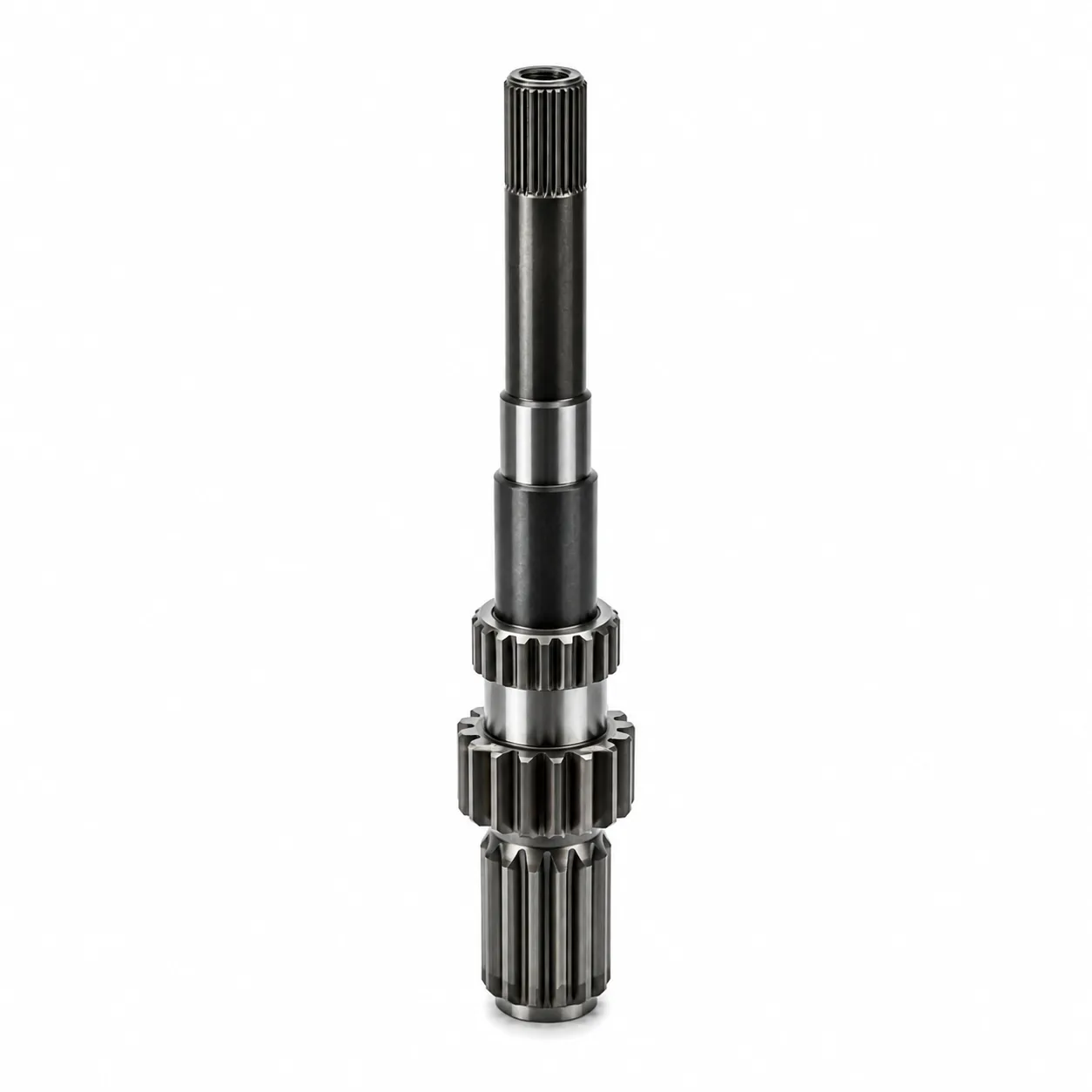
Gear and spline shaft interfaces combine multiple torque-transmitting and locating features on one component. The design should control how the gear, spline, journals and shoulders relate to common functional datums, especially when heat treatment and final finishing can affect runout or alignment.
Start with the load path
Identify where torque enters and leaves the spline connection, whether the interface is fixed or sliding, and what supports the shaft radially and axially. For integrated gears, splines, journals and datum relationships, this prevents the spline from being treated as an isolated tooth form. The same module and tooth count can behave differently when engagement, alignment or lubrication changes.
Record normal torque, peak or shock torque, speed, reversals, duty cycle and environmental exposure. If those values are not yet known, identify the machine class and failure consequences so the design review can focus on the most important uncertainties.
Define the interface on the drawing
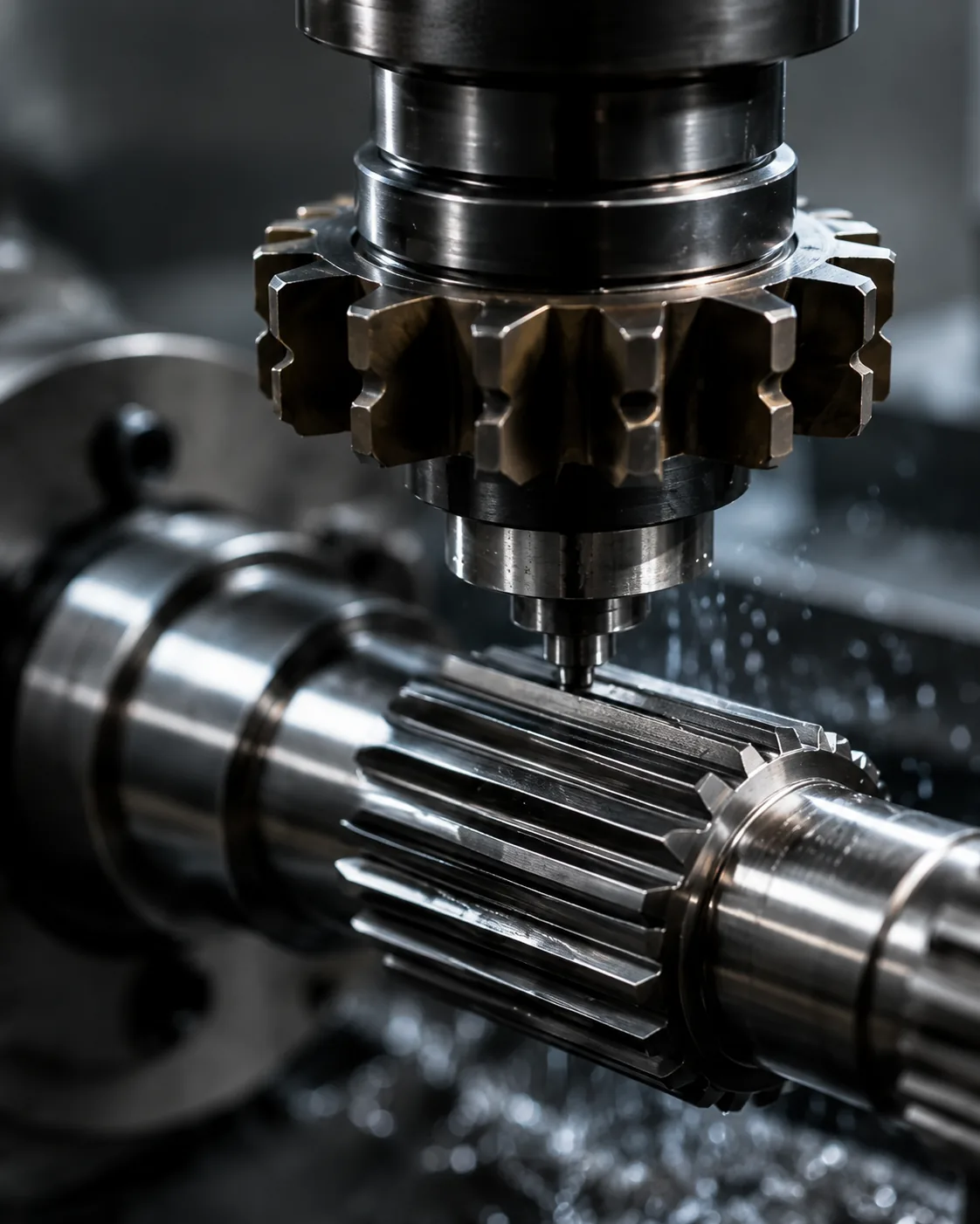
A complete spline definition usually needs the pitch system, tooth count, pressure angle, major and minor diameters, engagement, fit or accuracy basis and any end relief. The drawing should also identify the datum that relates the spline to bearing journals, gears, shoulders or seals. Avoid using a generic product name as a substitute for these dimensions.
For replacement work, do not copy only the worn tooth thickness. Measure or inspect the mating part, check unworn regions and determine whether fretting, misalignment, pitting or looseness changed the original geometry.
Material and manufacturing review
Material and heat treatment should be chosen from load, section size, wear requirement, impact duty and process route. A hard surface can improve wear resistance, but it also changes distortion risk and may require finish machining or grinding. State the functional requirement and let the manufacturing review connect it to a qualified process.
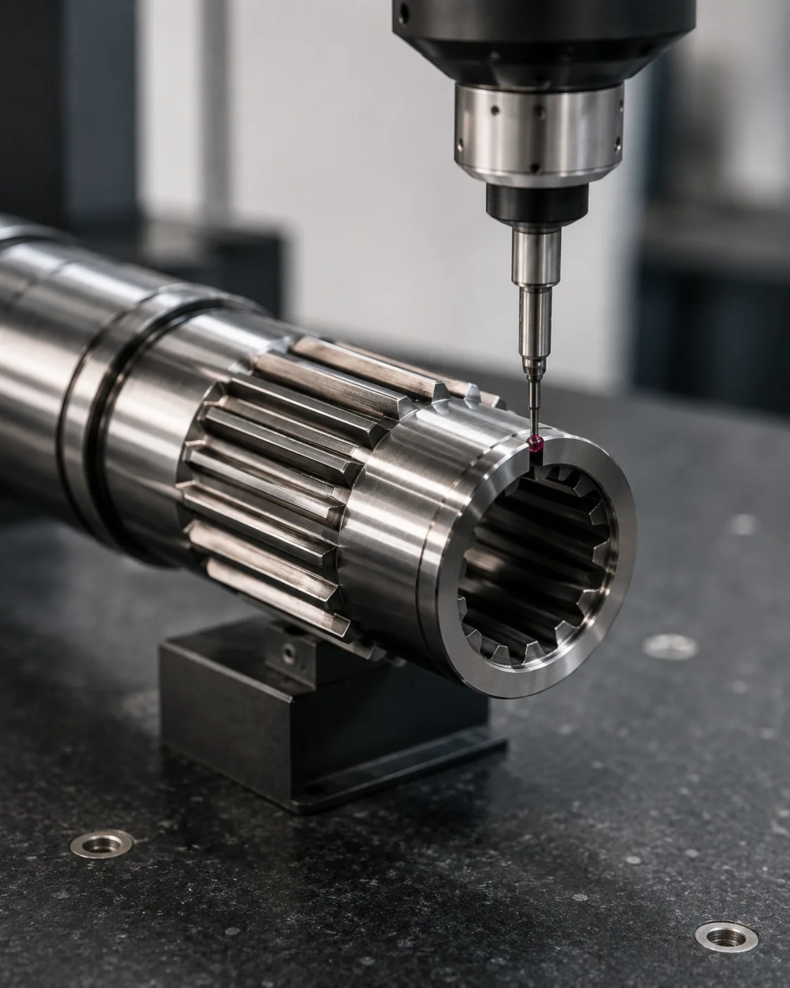
Inspection should be planned at the same time. Gage strategy, analytical measurement, CMM checks, runout inspection, roughness measurement and hardness testing answer different questions. Put acceptance criteria on the drawing so the inspection method has a defined purpose.
RFQ checklist
- Controlled 2D drawing and current revision
- Mating spline or hub details
- Material, heat treatment and hardness requirements
- Torque, speed, shock/reversing load and environment
- Quantity, first-article needs and inspection reporting
Send the controlled drawing, mating-interface definition, material, heat treatment, hardness, quantity, torque and speed, assembly method, environment and inspection-report expectations. If a sample is available, explain whether it is new, worn or failed and include the mating component where possible.
Review gear and spline shafts and fit and tolerance guidance as the next step before submitting the RFQ.
Questions engineers commonly ask
These questions appear repeatedly during spline-shaft RFQ reviews because they sit at the boundary between geometry, manufacturing and assembly. The answers are deliberately conditional: a spline connection cannot be qualified from a family name or image alone. Use the answers to identify what must be added to the drawing or duty description, and carry the agreed interpretation into inspection and first-article approval.
Can the spline be selected from nominal shaft diameter alone?
No. The tooth system, engagement, pressure angle, fit, datums and mating component define the interface. The final decision should be tied to the actual drawing and operating duty rather than a family-level assumption. Record the mating member, datum basis and acceptance method used to reach the decision, because those details determine whether later measurement results are comparable. For replacement work, inspect both members before assuming the original fit can be reconstructed from one worn component.
Should the process be specified on the drawing?
Only when a qualified process is functionally required. Otherwise define the required geometry, material condition and acceptance criteria. The final decision should be tied to the actual drawing and operating duty rather than a family-level assumption. Record the mating member, datum basis and acceptance method used to reach the decision, because those details determine whether later measurement results are comparable. For replacement work, inspect both members before assuming the original fit can be reconstructed from one worn component.
What causes many field problems?
Misalignment, insufficient engagement, poor fit control, inadequate lubrication for sliding splines and reproducing worn replacement geometry are common investigation areas. The final decision should be tied to the actual drawing and operating duty rather than a family-level assumption. Record the mating member, datum basis and acceptance method used to reach the decision, because those details determine whether later measurement results are comparable. For replacement work, inspect both members before assuming the original fit can be reconstructed from one worn component.
What should be inspected first on a replacement?
Check both mating members, contact pattern, wear symmetry, runout and the features that locate the shaft in the assembly. The final decision should be tied to the actual drawing and operating duty rather than a family-level assumption. Record the mating member, datum basis and acceptance method used to reach the decision, because those details determine whether later measurement results are comparable. For replacement work, inspect both members before assuming the original fit can be reconstructed from one worn component.
Release review and document control
Before releasing gear and spline shaft interfaces, verify that geometry, material, heat treatment, fit, datum structure, manufacturing sequence and inspection method describe one coherent component. A tight tolerance is not useful if it references the wrong datum; a hardness value is incomplete if the measurement location is undefined; and a spline callout is incomplete if the mating interface is not known. This cross-check is especially important when an existing part is being reverse-engineered from service.
Document revision status, open technical questions and the agreed measurement methods before first article. If the mating component or operating duty changes, repeat the compatibility review rather than assuming the spline remains interchangeable. Keep the approved drawing and inspection basis together so repeat orders can be compared to the same definition instead of recreating engineering decisions from email history.
First-article and repeat-order consistency
Use the first article to verify the complete datum chain, mating fit and inspection method, not only isolated tooth dimensions. Any accepted deviation should be captured formally and either incorporated into the drawing or closed before repeat production. This provides a stable reference for later maintenance and replacement work.
For recurring parts, retain measurement method, gage identification and drawing revision with the inspection record. Consistency is especially important for spline interfaces because two parts can appear visually similar while differing in tooth thickness, pressure angle, engagement or datum relationship.