Condition: New Warranty: Much more than 5 years Relevant Industries: Constructing Substance Retailers, Producing Plant, Machinery Restore Outlets, Foods & Beverage Factory, Printing Outlets, Building works , Vitality & Mining Showroom Place: None Video clip outgoing-inspection: Presented Equipment Check Report: Offered Marketing and advertising Variety: New Item 2571 Warranty of core components: A lot more than 5 many years Core Elements: other Construction: Spline Content: Alloy steel Coatings: Other Torque Potential: 33K N.m Model Variety: GJF20 Item identify: Ball Spline Accuracy Quality: 2/3/4 Nominal axial diameter: 16-a hundred and fifty Torsion clearance: P0/P1/P2 Static load: 8.1-221.3KN Exterior diameter: 23-135 Oil gap: 2-5 Place of oil hole: 13-55 Depth of counter bore: 4.4-17.5 Top quality: Large Precision After Warranty Services: Movie technological assistance, On the internet assistance, Spare areas, Discipline maintenance and mend support Nearby Service Location: None Packaging Specifics: Paper and wood box for 8.1-221.3KN static load 16-one hundred fifty nominal axial diameter shaft bearing prolonged steel spline shaft Port: ZheJiang
Item Overview Precision linear motion spline seriesThe spline is a kind of linear motion method. When spline motions along the precision floor Shaft by balls, the torque is transferred. The spline has compact construction. It can transfer the Over load and motive power. It has more time life time.At current the manufacturing facility manufacture 2 kinds of spline, namely convex spline and concave spline. Normally the convex spline can get larger radial load and torque than concave spline. Attributes AT A Look Ball sort:φ Large Torque Aluminum Substance Worm Gearbox RV Collection Worm Equipment Box with Output Flange Gear Box 16-φ250High speed , large accuracyHeavy load , prolonged lifeFlexible movement,reduced power consumptionHigh movement speedHeavy load and long provider lifeApplicationgs:semiconductor equipment,tire machinery,monocrystalline silicon furnace,health-related rehabilitation tools Solution Specifications
Xihu (West Lake) Dis.ye 40 many years Knowledgeable Manufacturing unit Manufactured 50Mm 12V 24V Worm Gearbox with Motor for Intelligent Home Appliance 02 -.3
+.12.50
+.230
+.230
+.240
Length of slot grooveI
20
26
36
26
40
Oil holed
2
3
3
3
3
Dynamic torsionN-m
38.nine
100
152.
192.2
288.nine
Stationary torsionN-m
105.9
270.five
345.
425.8
613.two
Dynamic loadC KN
5.5
10.719
13
16.3
19.three
Static loadC KN
13.three
25.499
26
33.one
36.one
GJZA Convex sort
Spec.
GJZA40
GJZA50
GJZA60
GJZA70
GJZA85
GJZA100
GJZA120
GJZA150
Nominal axial dia. d0
40
50
60
70
85
100
120
150
External dia.D
060-.019
075-.019
090-.571
5710-.571
0120-.571
0140-.571
0160-.571
5715-.571
Length of spline nut L1
5710-.three
0112-.3
0127-.three
0135-.three
0155-.three
0175-.4
5710-.four
5710-.four
Max. duration of shaft L
1500
1500
1500
1700
1900
1900
1900
1900
Width of slot groove b
10H8
14H8
16H8
18H8
20H8
28H8
28H8
32H8
Depth of slot groove t
+.250
+.twenty five.50
+.260
+.160
+.one hundred seventy
+.a hundred ninety
+.one hundred ninety
+.1100
Length of slot groove I
56
60
70
68
80
93
123
157
Oil hole d
4
4
4
4
5
5
6
6
Bike Chain Washer Cleansing Brush Chain Crank Sprocket Double-Sides Cleansing Washing Brushes Deal with Dynamic torsion N-m
651.nine
1048.
2135.9
3153.four
4437.two
6943.8
10153.5
19564.1
Stationary torsion N-m
1390.9
2200.7
4172.9
5797.six
8082.
11737.two
18779.5
33532.7
Dynamic load C KN
34.nine
44.nine
76.2
96.5
111.8
148.seven
181.three
279.four
Static load C0 KN
65.5
82.nine
131.one
156.1
179.2
221.3
295
421.5
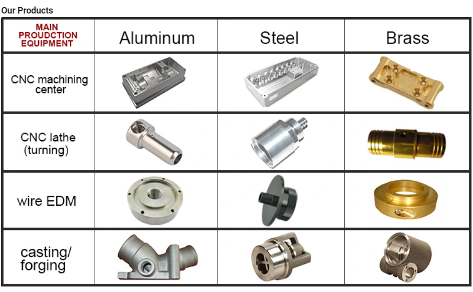
Manufacturing Tools 4m CNC linear CZPT grinding device straightening&quenching equipment Gap- punching equipment Income AND Support Network Equivalent Goods Effective Venture SYMG CZPT DMTG
How to Calculate Stiffness, Centering Force, Wear and Fatigue Failure of Spline Couplings
There are various types of spline couplings. These couplings have several important properties. These properties are: Stiffness, Involute splines, Misalignment, Wear and fatigue failure. To understand how these characteristics relate to spline couplings, read this article. It will give you the necessary knowledge to determine which type of coupling best suits your needs. Keeping in mind that spline couplings are usually spherical in shape, they are made of steel.
Involute splines
An effective side interference condition minimizes gear misalignment. When two splines are coupled with no spline misalignment, the maximum tensile root stress shifts to the left by five mm. A linear lead variation, which results from multiple connections along the length of the spline contact, increases the effective clearance or interference by a given percentage. This type of misalignment is undesirable for coupling high-speed equipment. Involute splines are often used in gearboxes. These splines transmit high torque, and are better able to distribute load among multiple teeth throughout the coupling circumference. The involute profile and lead errors are related to the spacing between spline teeth and keyways. For coupling applications, industry practices use splines with 25 to fifty-percent of spline teeth engaged. This load distribution is more uniform than that of conventional single-key couplings. To determine the optimal tooth engagement for an involved spline coupling, Xiangzhen Xue and colleagues used a computer model to simulate the stress applied to the splines. The results from this study showed that a “permissible” Ruiz parameter should be used in coupling. By predicting the amount of wear and tear on a crowned spline, the researchers could accurately predict how much damage the components will sustain during the coupling process. There are several ways to determine the optimal pressure angle for an involute spline. Involute splines are commonly measured using a pressure angle of 30 degrees. Similar to gears, involute splines are typically tested through a measurement over pins. This involves inserting specific-sized wires between gear teeth and measuring the distance between them. This method can tell whether the gear has a proper tooth profile. The spline system shown in Figure 1 illustrates a vibration model. This simulation allows the user to understand how involute splines are used in coupling. The vibration model shows four concentrated mass blocks that represent the prime mover, the internal spline, and the load. It is important to note that the meshing deformation function represents the forces acting on these three components.
Stiffness of coupling
The calculation of stiffness of a spline coupling involves the measurement of its tooth engagement. In the following, we analyze the stiffness of a spline coupling with various types of teeth using two different methods. Direct inversion and blockwise inversion both reduce CPU time for stiffness calculation. However, they require evaluation submatrices. Here, we discuss the differences between these two methods. The analytical model for spline couplings is derived in the second section. In the third section, the calculation process is explained in detail. We then validate this model against the FE method. Finally, we discuss the influence of stiffness nonlinearity on the rotor dynamics. Finally, we discuss the advantages and disadvantages of each method. We present a simple yet effective method for estimating the lateral stiffness of spline couplings. The numerical calculation of the spline coupling is based on the semi-analytical spline load distribution model. This method involves refined contact grids and updating the compliance matrix at each iteration. Hence, it consumes significant computational time. Further, it is difficult to apply this method to the dynamic analysis of a rotor. This method has its own limitations and should be used only when the spline coupling is fully investigated. The meshing force is the force generated by a misaligned spline coupling. It is related to the spline thickness and the transmitting torque of the rotor. The meshing force is also related to the dynamic vibration displacement. The result obtained from the meshing force analysis is given in Figures 7, 8, and 9. The analysis presented in this paper aims to investigate the stiffness of spline couplings with a misaligned spline. Although the results of previous studies were accurate, some issues remained. For example, the misalignment of the spline may cause contact damages. The aim of this article is to investigate the problems associated with misaligned spline couplings and propose an analytical approach for estimating the contact pressure in a spline connection. We also compare our results to those obtained by pure numerical approaches.
Misalignment
To determine the centering force, the effective pressure angle must be known. Using the effective pressure angle, the centering force is calculated based on the maximum axial and radial loads and updated Dudley misalignment factors. The centering force is the maximum axial force that can be transmitted by friction. Several published misalignment factors are also included in the calculation. A new method is presented in this paper that considers the cam effect in the normal force. In this new method, the stiffness along the spline joint can be integrated to obtain a global stiffness that is applicable to torsional vibration analysis. The stiffness of bearings can also be calculated at given levels of misalignment, allowing for accurate estimation of bearing dimensions. It is advisable to check the stiffness of bearings at all times to ensure that they are properly sized and aligned. A misalignment in a spline coupling can result in wear or even failure. This is caused by an incorrectly aligned pitch profile. This problem is often overlooked, as the teeth are in contact throughout the involute profile. This causes the load to not be evenly distributed along the contact line. Consequently, it is important to consider the effect of misalignment on the contact force on the teeth of the spline coupling. The centre of the male spline in Figure 2 is superposed on the female spline. The alignment meshing distances are also identical. Hence, the meshing force curves will change according to the dynamic vibration displacement. It is necessary to know the parameters of a spline coupling before implementing it. In this paper, the model for misalignment is presented for spline couplings and the related parameters. Using a self-made spline coupling test rig, the effects of misalignment on a spline coupling are studied. In contrast to the typical spline coupling, misalignment in a spline coupling causes fretting wear at a specific position on the tooth surface. This is a leading cause of failure in these types of couplings.
Wear and fatigue failure
The failure of a spline coupling due to wear and fatigue is determined by the first occurrence of tooth wear and shaft misalignment. Standard design methods do not account for wear damage and assess the fatigue life with big approximations. Experimental investigations have been conducted to assess wear and fatigue damage in spline couplings. The tests were conducted on a dedicated test rig and special device connected to a standard fatigue machine. The working parameters such as torque, misalignment angle, and axial distance have been varied in order to measure fatigue damage. Over dimensioning has also been assessed. During fatigue and wear, mechanical sliding takes place between the external and internal splines and results in catastrophic failure. The lack of literature on the wear and fatigue of spline couplings in aero-engines may be due to the lack of data on the coupling’s application. Wear and fatigue failure in splines depends on a number of factors, including the material pair, geometry, and lubrication conditions. The analysis of spline couplings shows that over-dimensioning is common and leads to different damages in the system. Some of the major damages are wear, fretting, corrosion, and teeth fatigue. Noise problems have also been observed in industrial settings. However, it is difficult to evaluate the contact behavior of spline couplings, and numerical simulations are often hampered by the use of specific codes and the boundary element method. The failure of a spline gear coupling was caused by fatigue, and the fracture initiated at the bottom corner radius of the keyway. The keyway and splines had been overloaded beyond their yield strength, and significant yielding was observed in the spline gear teeth. A fracture ring of non-standard alloy steel exhibited a sharp corner radius, which was a significant stress raiser. Several components were studied to determine their life span. These components include the spline shaft, the sealing bolt, and the graphite ring. Each of these components has its own set of design parameters. However, there are similarities in the distributions of these components. Wear and fatigue failure of spline couplings can be attributed to a combination of the three factors. A failure mode is often defined as a non-linear distribution of stresses and strains.
21618-Travel SHAFT 30% T/T in advance , 70% balance ahead of shippment . Or L/C .If you have one more concern, pls feel cost-free to contact us as underneath:
How to Calculate Stiffness, Centering Force, Wear and Fatigue Failure of Spline Couplings
There are various types of spline couplings. These couplings have several important properties. These properties are: Stiffness, Involute splines, Misalignment, Wear and fatigue failure. To understand how these characteristics relate to spline couplings, read this article. It will give you the necessary knowledge to determine which type of coupling best suits your needs. Keeping in mind that spline couplings are usually spherical in shape, they are made of steel.
Involute splines
An effective side interference condition minimizes gear misalignment. When two splines are coupled with no spline misalignment, the maximum tensile root stress shifts to the left by five mm. A linear lead variation, which results from multiple connections along the length of the spline contact, increases the effective clearance or interference by a given percentage. This type of misalignment is undesirable for coupling high-speed equipment. Involute splines are often used in gearboxes. These splines transmit high torque, and are better able to distribute load among multiple teeth throughout the coupling circumference. The involute profile and lead errors are related to the spacing between spline teeth and keyways. For coupling applications, industry practices use splines with 25 to fifty-percent of spline teeth engaged. This load distribution is more uniform than that of conventional single-key couplings. To determine the optimal tooth engagement for an involved spline coupling, Xiangzhen Xue and colleagues used a computer model to simulate the stress applied to the splines. The results from this study showed that a “permissible” Ruiz parameter should be used in coupling. By predicting the amount of wear and tear on a crowned spline, the researchers could accurately predict how much damage the components will sustain during the coupling process. There are several ways to determine the optimal pressure angle for an involute spline. Involute splines are commonly measured using a pressure angle of 30 degrees. Similar to gears, involute splines are typically tested through a measurement over pins. This involves inserting specific-sized wires between gear teeth and measuring the distance between them. This method can tell whether the gear has a proper tooth profile. The spline system shown in Figure 1 illustrates a vibration model. This simulation allows the user to understand how involute splines are used in coupling. The vibration model shows four concentrated mass blocks that represent the prime mover, the internal spline, and the load. It is important to note that the meshing deformation function represents the forces acting on these three components.
Stiffness of coupling
The calculation of stiffness of a spline coupling involves the measurement of its tooth engagement. In the following, we analyze the stiffness of a spline coupling with various types of teeth using two different methods. Direct inversion and blockwise inversion both reduce CPU time for stiffness calculation. However, they require evaluation submatrices. Here, we discuss the differences between these two methods. The analytical model for spline couplings is derived in the second section. In the third section, the calculation process is explained in detail. We then validate this model against the FE method. Finally, we discuss the influence of stiffness nonlinearity on the rotor dynamics. Finally, we discuss the advantages and disadvantages of each method. We present a simple yet effective method for estimating the lateral stiffness of spline couplings. The numerical calculation of the spline coupling is based on the semi-analytical spline load distribution model. This method involves refined contact grids and updating the compliance matrix at each iteration. Hence, it consumes significant computational time. Further, it is difficult to apply this method to the dynamic analysis of a rotor. This method has its own limitations and should be used only when the spline coupling is fully investigated. The meshing force is the force generated by a misaligned spline coupling. It is related to the spline thickness and the transmitting torque of the rotor. The meshing force is also related to the dynamic vibration displacement. The result obtained from the meshing force analysis is given in Figures 7, 8, and 9. The analysis presented in this paper aims to investigate the stiffness of spline couplings with a misaligned spline. Although the results of previous studies were accurate, some issues remained. For example, the misalignment of the spline may cause contact damages. The aim of this article is to investigate the problems associated with misaligned spline couplings and propose an analytical approach for estimating the contact pressure in a spline connection. We also compare our results to those obtained by pure numerical approaches.
Misalignment
To determine the centering force, the effective pressure angle must be known. Using the effective pressure angle, the centering force is calculated based on the maximum axial and radial loads and updated Dudley misalignment factors. The centering force is the maximum axial force that can be transmitted by friction. Several published misalignment factors are also included in the calculation. A new method is presented in this paper that considers the cam effect in the normal force. In this new method, the stiffness along the spline joint can be integrated to obtain a global stiffness that is applicable to torsional vibration analysis. The stiffness of bearings can also be calculated at given levels of misalignment, allowing for accurate estimation of bearing dimensions. It is advisable to check the stiffness of bearings at all times to ensure that they are properly sized and aligned. A misalignment in a spline coupling can result in wear or even failure. This is caused by an incorrectly aligned pitch profile. This problem is often overlooked, as the teeth are in contact throughout the involute profile. This causes the load to not be evenly distributed along the contact line. Consequently, it is important to consider the effect of misalignment on the contact force on the teeth of the spline coupling. The centre of the male spline in Figure 2 is superposed on the female spline. The alignment meshing distances are also identical. Hence, the meshing force curves will change according to the dynamic vibration displacement. It is necessary to know the parameters of a spline coupling before implementing it. In this paper, the model for misalignment is presented for spline couplings and the related parameters. Using a self-made spline coupling test rig, the effects of misalignment on a spline coupling are studied. In contrast to the typical spline coupling, misalignment in a spline coupling causes fretting wear at a specific position on the tooth surface. This is a leading cause of failure in these types of couplings.
Wear and fatigue failure
The failure of a spline coupling due to wear and fatigue is determined by the first occurrence of tooth wear and shaft misalignment. Standard design methods do not account for wear damage and assess the fatigue life with big approximations. Experimental investigations have been conducted to assess wear and fatigue damage in spline couplings. The tests were conducted on a dedicated test rig and special device connected to a standard fatigue machine. The working parameters such as torque, misalignment angle, and axial distance have been varied in order to measure fatigue damage. Over dimensioning has also been assessed. During fatigue and wear, mechanical sliding takes place between the external and internal splines and results in catastrophic failure. The lack of literature on the wear and fatigue of spline couplings in aero-engines may be due to the lack of data on the coupling’s application. Wear and fatigue failure in splines depends on a number of factors, including the material pair, geometry, and lubrication conditions. The analysis of spline couplings shows that over-dimensioning is common and leads to different damages in the system. Some of the major damages are wear, fretting, corrosion, and teeth fatigue. Noise problems have also been observed in industrial settings. However, it is difficult to evaluate the contact behavior of spline couplings, and numerical simulations are often hampered by the use of specific codes and the boundary element method. The failure of a spline gear coupling was caused by fatigue, and the fracture initiated at the bottom corner radius of the keyway. The keyway and splines had been overloaded beyond their yield strength, and significant yielding was observed in the spline gear teeth. A fracture ring of non-standard alloy steel exhibited a sharp corner radius, which was a significant stress raiser. Several components were studied to determine their life span. These components include the spline shaft, the sealing bolt, and the graphite ring. Each of these components has its own set of design parameters. However, there are similarities in the distributions of these components. Wear and fatigue failure of spline couplings can be attributed to a combination of the three factors. A failure mode is often defined as a non-linear distribution of stresses and strains.
Q: Is the business a manufacturing manufacturing facility or a buying and selling business? A: HangZhou Best Bearing Co.,Ltd. is a manufacturing business concentrating on bearings and integrating analysis, manufacturing and sales.
Q: How a lot of the MOQ of your company? A: Depending on the measurement of the bearing, the MOQ is variable, if you are intrigued, you can get in touch with me for a estimate.
Q: Does the organization settle for OEM or custom-made bearings? A: In addition to standard goods, we also offer non-common and modified standard items for special software. In the meantime, we provide OEM provider.
Q: How about the creation time? A: Typically 5-10 days if we get the inventory.
Q: Do you offer samples? A: We can supply samples for free. You only want to offer delivery.
Q: What is your payment conditions? A: 30% as deposit, and the harmony prior to cargo.
Q: Can you organize door to doorway shipping? A: Sure, we can quotation based on DDP, doorway to door, duty compensated.
Splined shafts are the most common types of bearings for machine tools. They are made of a wide variety of materials, including metals and non-metals such as Delrin and nylon. They are often fabricated to reduce deflection. The tooth profile will become deformed with time, as the shaft is used over a long period of time. Splined shafts are available in a huge range of materials and lengths.
Functions
Splined shafts are used in a variety of applications and industries. They are an effective anti-rotational device, as well as a reliable means of transmitting torque. Other types of shafts are available, including key shafts, but splines are the most convenient for transmitting torque. The following article discusses the functions of splines and why they are a superior choice. Listed below are a few examples of applications and industries in which splines are used. Splined shafts can be of several styles, depending on the application and mechanical system in question. The differences between splined shaft styles include the design of teeth, overall strength, transfer of rotational concentricity, sliding ability, and misalignment tolerance. Listed below are a few examples of splines, as well as some of their benefits. The difference between these styles is not mutually exclusive; instead, each style has a distinct set of pros and cons. A splined shaft is a cylindrical shaft with teeth or ridges that correspond to a specific angular position. This allows a shaft to transfer torque while maintaining angular correspondence between tracks. A splined shaft is defined as a cylindrical member with several grooves cut into its circumference. These grooves are equally spaced around the shaft and form a series of projecting keys. These features give the shaft a rounded appearance and allow it to fit perfectly into a grooved cylindrical member. While the most common applications of splines are for shortening or extending shafts, they can also be used to secure mechanical assemblies. An “involute spline” spline has a groove that is wider than its counterparts. The result is that a splined shaft will resist separation during operation. They are an ideal choice for applications where deflection is an issue. A spline shaft’s radial torsion load distribution is equally distributed, unless a bevel gear is used. The radial torsion load is evenly distributed and will not exert significant load concentration. If the spline couplings are not aligned correctly, the spline connection can fail quickly, causing significant fretting fatigue and wear. A couple of papers discuss this issue in more detail.
Types
There are many different types of splined shafts. Each type features an evenly spaced helix of grooves on its outer surface. These grooves are either parallel or involute. Their shape allows them to be paired with gears and interchange rotary and linear motion. Splines are often cold-rolled or cut. The latter has increased strength compared to cut spines. These types of shafts are commonly used in applications requiring high strength, accuracy, and smoothness. Another difference between internal and external splined shafts lies in the manufacturing process. The former is made of wood, while the latter is made of steel or a metal alloy. The process of manufacturing splined shafts involves cutting furrows into the surface of the material. Both processes are expensive and require expert skill. The main advantage of splined shafts is their adaptability to a wide range of applications. In general, splined shafts are used in machinery where the rotation is transferred to an internal splined member. This member can be a gear or some other rotary device. These types of shafts are often packaged together as a hub assembly. Cleaning and lubricating are essential to the life of these components. If you’re using them on a daily basis, you’ll want to make sure to regularly inspect them. Crowned splines are usually involute. The teeth of these splines form a spiral pattern. They are used for smaller diameter shafts because they add strength. Involute splines are also used on instrument drives and valve shafts. Serration standards are found in the SAE. Both kinds of splines can also contain a ball bearing for high torque. The difference between the two types of splines is the number of teeth on the shaft. Internal splines have many advantages over external ones. For example, an internal spline shaft can be made using a grinding wheel instead of a CNC machine. It also uses a more accurate and economical process. Furthermore, it allows for a shorter manufacturing cycle, which is essential when splining high-speed machines. In addition, it stabilizes the relative phase between the spline and thread.
Manufacturing methods
There are several methods used to fabricate a splined shaft. Key and splined shafts are constructed from two separate parts that are shaped in a synchronized manner to transfer torque uniformly. Hot rolling is one method, while cold rolling utilizes low temperatures to form metal. Both methods enhance mechanical properties, surface finishes, and precision. The advantage of cold rolling is its cost-effectiveness. Cold forming is one method, as well as machining and assembling. Cold forming is a unique process that allows the spline to be shaped to the desired shape. The resulting shape provides maximum contact area and torsional strength. Standard splines are available in standard sizes, but custom lengths can also be ordered. CZPT offers various auxiliary equipment, such as mating sleeves and flanged bushings. Cold forging is another method. This method produces long splined shafts that are used in automobile propellers. After the spline portion is cut out, it is worked on in a hobbing machine. Work hardening enhances the root strength of the splined portion. It can be used for bearings, gears, and other mechanical components. Listed below are the manufacturing methods for splined shafts. Parallel splines are the simplest of the splined shaft manufacturing methods. Parallel splines are usually welded to shafts, while involute splines are made of metal or non-metals. Splines are available in a wide variety of lengths and materials. The process is usually accompanied by a process called milling. The workpiece rotates to produce the serrated surface. Splines are internal or external grooves in a splined shaft. They work in combination with keyways to transfer torque. Male and female splines are used in gears. Female and male splines correspond to one another to ensure proper angular correspondence. Involute splines have more surface area and thus are stronger than external splines. Moreover, they help the shaft fit into a grooved cylindrical member without misalignment. A variety of other methods of manufacturing a splined shaft can be used to produce a splined shaft. Spline shafts can be produced using broaching and shaping, two precision machining methods. Broaching uses a metal tool with successively larger teeth to remove metal and create ridges and holes in the surface of a material. However, this process is expensive and requires special expertise.
Applications
The splined shaft is a mechanical component with a helix-like shape formed by the equal spacing of grooves in a circular ring. The splines can either have parallel or involute sides. The splines minimize stress concentration in stationary joints and can be used in both rotary and linear motion. In some cases, splines are rolled rather than cut. The latter is more durable than cut splines and is often used in applications requiring high strength, accuracy, and smooth finish. Splined shafts are commonly made of carbon steel. This alloy steel has a low carbon content, making it easy to work with. Carbon steel is a great choice for splines because it is malleable. Generally, high-quality carbon steel provides a consistent motion. Steel alloys are also available that contain nickel, chromium, copper, and other metals. If you’re unsure of the right material for your application, you can consult a spline chart. Splines are a versatile mechanical component. They are easy to cut and fit. Splines can be internal or external, with teeth positioned at equal intervals on both sides of the shaft. This allows the shaft to engage with the hub around the entire circumference of the hub. It also increases load capacity by creating a constant multiple-tooth point of contact with the hub. For this reason, they’re used extensively in rotary and linear motion. Splined shafts are used in a wide variety of industries. CZPT Inc. offers custom and standard splined shafts for a variety of applications. When choosing a splined shaft for a specific application, consider the surrounding mated components, torque requirements, and size requirements. These three factors will make it the ideal choice for your rotary equipment. And you’ll be pleased with the end result! There are many types of splines and their applications are endless. They transfer torque and angular misalignment between parts, and they also enable the axial rotation of assembled components. Therefore, splines are an essential component of machinery and are used in a wide range of applications. This type of shaft can be found in various types of machines, from household appliances to industrial machinery. So, the next time you’re looking for a splined shaft, make sure you look for a splined one.
PTO shafts range in dimensions and you will need to find a matching coupling to drag. Attaching the instrument to the tractor must be simple. If you have to elevate the unit off the ground to hook up to the driveshaft, or if the driveshaft is too long, forcing the relationship could harm each. If you have an present PTO shaft handy, it really is effortless to affirm your size. Close it and evaluate from PTO yoke to yoke.
A single aspect of our software consulting is that we have been amassing and combining the knowledge in chain and sprocket applications in numerous areas for many years. This is especially interesting for us each time clients strategy us with some exceeding and tough demands.In this way, our goods have ongoing to achieve market acceptance and consumers satisfaction in excess of the previous few many years.
Overview
Swift Information
Relevant Industries:
Producing Plant
Manufacturer Identify:
OEM
OEM Service:
Help
Tolerance:
.01-.05mm or Personalized
Certification:
ISO9001, SGS
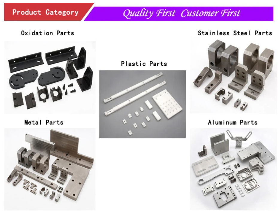
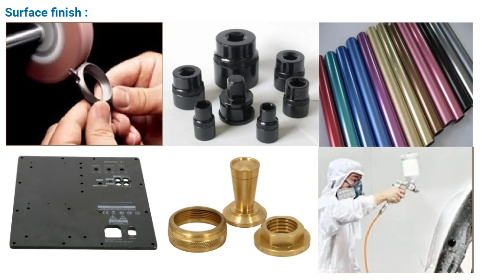
Surface Remedy:
Sandblasting,Polishing,Anodize, Zinc,Nickel,Chrome,Plating, and so on.
Software:
Vehicle,Health-related EquipmentThis novel breather plug attributes a spring that helps prevent oil bubbles from forming and percolating to the exterior.s,Electric Appliance,Hardware,etc.
Dimension:
As Customers’ Request
Gear:
Milling/Lathe/Drilling/Four/A few Axis CNC Machining Middle
To offer generation layout, creation and technical service, mould development and processing, etc
Drawing Format:
PRO/E, Auto CAD, Solid Works,IGS,UG, CAD/CAM/CAE
Testing Equipment
Digital Peak Gauge, caliper, Coordinate measuring equipment, projection equipment, roughness tester, hardness tester and so oClose up of two yokes with the universal joint. Notice the slight oozing of grease from the UJ seal finishes, the clump of grease is from inside of the yoke splined shaft region –Drive (outer) yoke has a woman (common spline) gap and “Y” form end that is the common joint (UJ) mount. –UJ is a cross formed casting getting roller bearings enclosed with caps at all 4 details and is held into the yoke with 4 “C” clips –Inner yoke and generate shaft is one more yoke welded to the push finish, of the travel shaft. –Pushed shaft and internal yoke is the pushed shaft that rides inside of the push shaft and has a yoke welded at the driven conclude –UJ yet another UJ as aboven
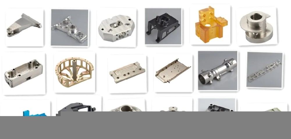
Industry employed
Machinery heavy obligation tools electronic unit Car spare elements optical telecommunication
Packing
Eco-welcoming pp bag / EPE Foam /Carton packing containers or wooden boxes As customer’s distinct demands