Gear and Spline Shafts for Compact Power Transmission Layouts — Combining a gear and spline on one shaft can reduce separate joints and axial stack-up, but it also makes datum control, heat-treatment distortion and inspection of feature relationships more important. The assembly drawing should define how gear, spline, journals and shoulders work together.
For gear and spline shaft, the most reliable specification is the one that a designer, buyer, manufacturer and inspector can all interpret the same way. The discussion below focuses on measurable drawing inputs, assembly conditions and practical checks rather than universal torque, fit or life claims that cannot be determined without full geometry and duty data.
Part-Count Reduction
Part-Count Reduction should be reviewed in the context of gear and spline shaft. Identify the mating component, operating function and drawing feature that this decision controls. The requirement should be measurable and connected to fit, torque transfer, alignment, wear or another defined assembly need.
Consider the decision together with material condition, manufacturing sequence and inspection access. If the part is a replacement, compare unworn geometry and the mating member instead of copying damage. For new designs, keep open process choices flexible unless a specific process is itself required by the design. For this topic, connect that decision to the mating component and the drawing revision used for the RFQ. When reviewing gear and spline shaft, revisit this point whenever the mating component, material condition or operating duty changes.
Gear-To-Spline Datum Relationship
Gear-To-Spline Datum Relationship determines how the spline is located relative to the features that support rotation. Functional datums are normally chosen from journals, pilot diameters, shoulders or other surfaces that locate the component in the assembly. The tolerance should reproduce that relationship during inspection.
Avoid using geometric tolerances as isolated quality numbers. Decide what misalignment the assembly can tolerate, identify the datum reference frame, and specify the controlled feature. Heat treatment and final finishing can change the relationship, so the measurement should be performed at the production stage that represents the finished part. In this review, the useful acceptance criterion is the one that can be traced to a functional drawing characteristic. For Gear and Spline Shafts for Compact Power Transmission Layouts, apply this check to the specific gear and spline shaft interface shown on the current drawing.
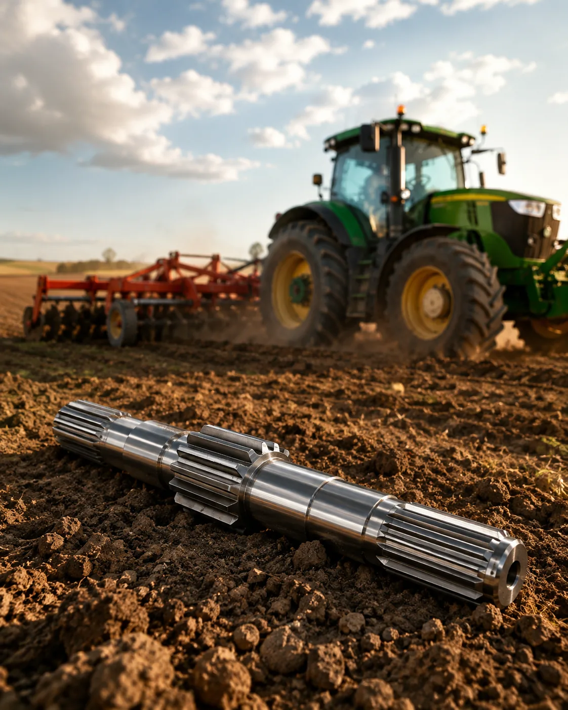
Bearing Journal Control
Bearing Journal Control determines how the spline is located relative to the features that support rotation. Functional datums are normally chosen from journals, pilot diameters, shoulders or other surfaces that locate the component in the assembly. The tolerance should reproduce that relationship during inspection.
Avoid using geometric tolerances as isolated quality numbers. Decide what misalignment the assembly can tolerate, identify the datum reference frame, and specify the controlled feature. Heat treatment and final finishing can change the relationship, so the measurement should be performed at the production stage that represents the finished part. For repeat work, keep the same datum and measurement basis unless the assembly requirement changes. For Gear and Spline Shafts for Compact Power Transmission Layouts, record the resulting requirement on the drawing or purchase specification so it remains consistent on repeat orders.
Heat-Treatment Distortion
Heat-Treatment Distortion influences wear resistance, fatigue behavior, distortion and the sequence of finish machining. Carburizing, induction hardening and quench-and-temper treatment create different material conditions, so they should not be treated as interchangeable ways to reach a hardness number.
Specify hardness with a location and, where required, case depth or core condition. If heat treatment can change straightness or feature relationship, plan the datum recovery and final inspection after the thermal process. Critical journals or tooth surfaces may need finish stock when tight tolerances must be restored. When the duty or mating member changes, revisit this point instead of carrying the previous assumption forward. For Gear and Spline Shafts for Compact Power Transmission Layouts, record the resulting requirement on the drawing or purchase specification so it remains consistent on repeat orders.
Long-Shaft Handling
Long-Shaft Handling should be reviewed in the context of gear and spline shaft. Identify the mating component, operating function and drawing feature that this decision controls. The requirement should be measurable and connected to fit, torque transfer, alignment, wear or another defined assembly need.
Consider the decision together with material condition, manufacturing sequence and inspection access. If the part is a replacement, compare unworn geometry and the mating member instead of copying damage. For new designs, keep open process choices flexible unless a specific process is itself required by the design. For this topic, connect that decision to the mating component and the drawing revision used for the RFQ. When reviewing gear and spline shaft, revisit this point whenever the mating component, material condition or operating duty changes.
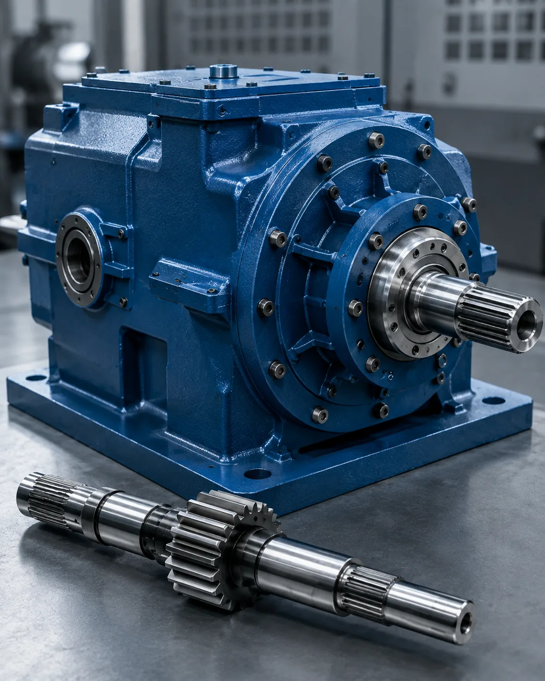
Assembly Stack-Up
Assembly Stack-Up places the spline in an operating context. Torque direction, shock loading, contamination, lubrication, axial movement, bearing support and service access can all change what fit and material condition are practical.
For an RFQ, describe the actual machine or assembly function and provide the mating component. Replacement requests should include wear photographs and measurements from unworn areas. This information helps separate geometry problems from alignment, lubrication or maintenance issues elsewhere in the system. In this review, the useful acceptance criterion is the one that can be traced to a functional drawing characteristic. When reviewing gear and spline shaft, revisit this point whenever the mating component, material condition or operating duty changes.
A practical review sequence
A practical review sequence starts with the mating component and torque path, then confirms tooth system, engagement and the shaft features that locate the connection. Next define material and heat treatment, functional finishes and any runout or position requirements. For repeat work, keep the same datum and measurement basis unless the assembly requirement changes. For Gear and Spline Shafts for Compact Power Transmission Layouts, apply this check to the specific gear and spline shaft interface shown on the current drawing.
Finish by agreeing the inspection method, quantity and first-article documentation. This order prevents process or tolerance decisions from being made before the functional interface is understood and makes quotations easier to compare because the same design inputs are presented to each supplier. When the duty or mating member changes, revisit this point instead of carrying the previous assumption forward. For Gear and Spline Shafts for Compact Power Transmission Layouts, apply this check to the specific gear and spline shaft interface shown on the current drawing.
Inspection Sequence
Inspection Sequence should use a method that measures the drawing characteristic directly or functionally. Functional gages, analytical tooth measurement, CMM inspection, span measurements and measurements over pins or balls answer different questions and are not interchangeable by default.
Agree the method before production when tolerance is tight or when customer and supplier use different equipment. Control temperature, cleanliness and gage calibration for repeatability. The inspection report should identify the drawing revision and datum setup so later lots can be compared on the same basis. For this topic, connect that decision to the mating component and the drawing revision used for the RFQ. For Gear and Spline Shafts for Compact Power Transmission Layouts, apply this check to the specific gear and spline shaft interface shown on the current drawing.
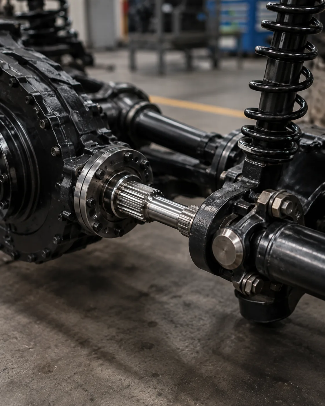
Serviceability Trade-Offs
Serviceability Trade-Offs places the spline in an operating context. Torque direction, shock loading, contamination, lubrication, axial movement, bearing support and service access can all change what fit and material condition are practical.
For an RFQ, describe the actual machine or assembly function and provide the mating component. Replacement requests should include wear photographs and measurements from unworn areas. This information helps separate geometry problems from alignment, lubrication or maintenance issues elsewhere in the system. In this review, the useful acceptance criterion is the one that can be traced to a functional drawing characteristic. In a gear and spline shaft RFQ, keep this point tied to the mating member, datum scheme and finished-part acceptance method.
Common mistakes to avoid
Common errors in gear and spline shaft come from treating one nominal value as if it defines the complete interface. Missing pressure angle, unclear datums, copied wear dimensions, unspecified hardness location and mismatched inspection methods can all create parts that look correct on paper but do not assemble consistently.
A better review starts with the mating pair, identifies the load path and locating features, then connects geometry, material condition and inspection to those functions. Close open questions on the drawing before production and retain the agreed interpretation with the revision for repeat orders. For repeat work, keep the same datum and measurement basis unless the assembly requirement changes. In a gear and spline shaft RFQ, keep this point tied to the mating member, datum scheme and finished-part acceptance method.
Decision summary
| Decision area | What to confirm | Why it matters |
|---|---|---|
| Mating geometry | Tooth system, diameters, engagement and fit | Controls compatibility and flank contact |
| Location | Datums, journals, shoulders and runout | Controls alignment in the assembly |
| Material condition | Grade, heat treatment, hardness and finish | Defines the finished mechanical and wear condition |
| Duty | Torque, speed, shock, movement and environment | Connects the part definition to operating conditions |
| Inspection | Controlled characteristics and measurement method | Keeps acceptance consistent between supplier and buyer |
Specification checklist
- Mating component and external/internal tooth orientation
- Module or pitch system, tooth count, pressure angle and major/minor diameters
- Effective engagement, fit or tolerance basis and axial movement if required
- Material, heat treatment, hardness location and functional surface finishes
- Datums, bearing or pilot diameters, runout and axial location requirements
- Torque, speed, shock or reversing load, lubrication and operating environment
- Quantity, first-article requirements and agreed inspection documentation
Use the spline shaft product range to compare available configurations and the RFQ drawing checklist to prepare a complete enquiry. When the duty or mating member changes, revisit this point instead of carrying the previous assumption forward. In a gear and spline shaft RFQ, keep this point tied to the mating member, datum scheme and finished-part acceptance method.
Engineering worksheet for gear and spline shaft
Use this worksheet to turn Gear and Spline Shafts for Compact Power Transmission Layouts into decisions that can be shown on a drawing, checked during quotation and verified at first article. Begin with Part-Count Reduction and Gear-To-Spline Datum Relationship, because those two items usually define either the mating geometry or the material condition that the rest of the process must support. Then review Bearing Journal Control, Heat-Treatment Distortion and Long-Shaft Handling against the actual assembly rather than treating them as independent catalogue values.
For an application review, describe the complete connection: driver and driven member, bearing support, axial restraint, assembly access and the environment around the spline. Add torque, speed, shock or reversing load, contamination, lubrication and any sliding movement. The same nominal tooth system can behave differently when engagement, stiffness, alignment or duty changes, so interface selection should follow the actual operating context. For Gear and Spline Shafts for Compact Power Transmission Layouts, apply this check to the specific gear and spline shaft interface shown on the current drawing.
Use part-count reduction and heat-treatment distortion as assembly checkpoints. Confirm the mating part, verify that the available engagement is real working length rather than chamfer or relief, and check that the locating journals or shoulders establish the intended alignment. For service replacements, inspect both members before ordering; a new shaft cannot correct excessive wear or damage in the mating hub by itself.
Drawing review sequence
Before requesting production, review the drawing in the same order that the assembly works: mating tooth system, effective engagement, locating datums, adjacent journals or shoulders, material and heat treatment, functional finishes, and inspection method. For gear and spline shaft, the order matters because later decisions such as process selection or gage choice should support the interface rather than redefine it.
| Worksheet item | Question to answer | RFQ output |
|---|---|---|
| Part-Count Reduction | What assembly function does this feature control? | Dimension, tolerance or mating reference |
| Gear-To-Spline Datum Relationship | What finished condition must be achieved? | Material / heat-treatment / finish callout |
| Bearing Journal Control | How will the characteristic be verified? | Inspection method or reporting note |
| Heat-Treatment Distortion | How does the opposite member engage? | Mating-part and engagement information |
| Long-Shaft Handling | Which datum establishes functional location? | Datum and runout relationship |
Procurement handoff before first article
A useful purchasing package for Gear and Spline Shafts for Compact Power Transmission Layouts contains the controlled drawing, quantity, material and heat-treatment condition, mating-interface information and the acceptance characteristics that require reporting. If a 3D model is supplied, the 2D drawing should still carry tolerances, datums, heat-treatment notes and inspection requirements. Identify the current revision in the RFQ so manufacturing and inspection do not work from different versions.
When a characteristic is not yet decided, mark it for engineering clarification rather than inserting a convenient value. For gear and spline shaft, common open items are engagement, fit, hardness location, runout to an adjacent journal, internal-feature access or the condition of a worn mating component. Resolving those points before first article reduces avoidable rework and makes later repeat orders easier to control.
Pre-release checklist
- Confirm part-count reduction against the actual mating component.
- Confirm gear-to-spline datum relationship in the finished condition.
- Define how bearing journal control will be inspected.
- Check heat-treatment distortion under the intended assembly condition.
- Relate long-shaft handling to the functional datum structure.
- State quantity, revision level and any first-article documentation requirement.
- Record changes in duty, lubrication or mating hardware for repeat orders.
Frequently asked questions
What should I confirm about part-count reduction for gear and spline shaft?
Relate part-count reduction to the mating component and the assembly function first. Put the measurable requirement on the controlled drawing, and include the opposite member when compatibility depends on both parts. For Gear and Spline Shafts for Compact Power Transmission Layouts, this prevents a nominal label from replacing the geometry that actually controls fit and torque transfer.
What should I confirm about gear-to-spline datum relationship for gear and spline shaft?
Confirm gear-to-spline datum relationship in the finished condition, including any material, heat-treatment, surface or dimensional state that can change after processing. If the requirement depends on a location or datum, show that explicitly so production and inspection use the same reference.
What should I confirm about bearing journal control for gear and spline shaft?
Choose an inspection method that measures the characteristic named on the drawing. Functional gaging, analytical spline measurement, CMM checks, runout inspection, roughness measurement and hardness testing answer different questions. State which result is required for acceptance rather than requesting a generic inspection report. In a gear and spline shaft RFQ, keep this point tied to the mating member, datum scheme and finished-part acceptance method.
What should I confirm about heat-treatment distortion for gear and spline shaft?
Check heat-treatment distortion with the real mating part and intended assembly condition. Effective engagement, clearance, axial movement, temperature and wear in a replacement hub can all influence how the connection behaves. A new shaft should not be accepted or rejected from feel alone when a measurable fit requirement is available.
What should I confirm about long-shaft handling for gear and spline shaft?
Tie long-shaft handling to the features that locate rotation in the assembly. The drawing should make the datum reference and any runout or position relationship clear. If heat treatment or finish machining can move the feature, inspect the relationship at the stage that represents the finished part.
From engineering decision to production control
Once the interface is agreed, translate each functional decision into a drawing characteristic that can be manufactured and inspected. Avoid leaving key relationships only in email notes. Dimensions, datums, heat-treatment conditions and acceptance requirements should be revision-controlled so the production team and inspection team work to the same definition. For repeat work, keep the same datum and measurement basis unless the assembly requirement changes. For Gear and Spline Shafts for Compact Power Transmission Layouts, record the resulting requirement on the drawing or purchase specification so it remains consistent on repeat orders.
For first articles, prioritize the characteristics that prove assembly compatibility: tooth geometry, mating fit, relationship to locating journals or shoulders, heat-treatment condition and any critical runout. Record the measurement method together with the result. On repeat orders, using the same datum setup and measurement approach makes trend changes easier to recognize and reduces disputes caused by different inspection interpretations. When the duty or mating member changes, revisit this point instead of carrying the previous assumption forward. When reviewing gear and spline shaft, revisit this point whenever the mating component, material condition or operating duty changes.
When the operating duty changes, reopen the engineering review instead of assuming the old specification remains suitable. Higher torque, increased shock, more frequent reversals, different lubrication or a new mating component can change contact and wear even if the nominal spline size stays the same. The drawing should evolve with the actual assembly requirement. For this topic, connect that decision to the mating component and the drawing revision used for the RFQ. In a gear and spline shaft RFQ, keep this point tied to the mating member, datum scheme and finished-part acceptance method.
Prepare the RFQ
- Current 2D drawing and revision
- Mating component and spline definition
- Material, heat treatment and functional finishes
- Torque, speed, duty and environment
- Quantity and required inspection documentation
A complete enquiry combines the drawing, mating interface, material condition, duty, quantity and inspection expectations. When these inputs are defined early, suppliers can plan tooling, heat treatment, finishing and measurement around the same functional requirement, reducing clarification cycles before first article. In this review, the useful acceptance criterion is the one that can be traced to a functional drawing characteristic. For Gear and Spline Shafts for Compact Power Transmission Layouts, record the resulting requirement on the drawing or purchase specification so it remains consistent on repeat orders.
Turn the guide into an RFQ
Send the controlled drawing, mating interface, material condition and duty information for technical review.
Request a Quote