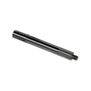
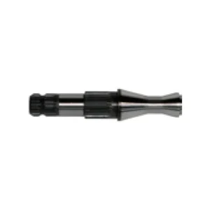
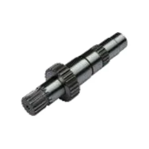
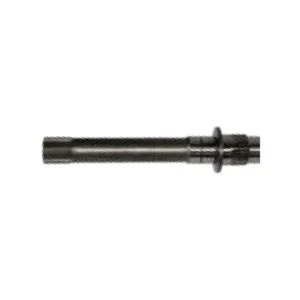
External Spline Shafts
Compare spline-shaft families by mating interface, material condition and drawing requirements.
External Spline Shafts
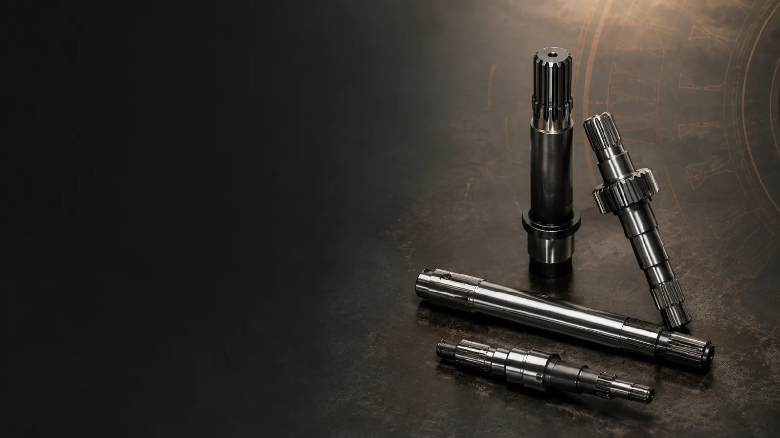
External Spline Shafts are best specified as engineered interfaces rather than as generic steel shafts. The useful starting point is the mating geometry: tooth form, module or pitch system, tooth count, pressure angle, engagement length, fit strategy, material condition and the shaft features that locate the part in the assembly. This category focuses on male spline features that engage mating hubs, gears, yokes or sleeves. For quotation, a controlled drawing or a dimensioned interface sketch is more valuable than a nominal shaft diameter alone.
What buyers need to define first
The first decision is not material or heat treatment; it is the geometry of the connection. A external spline shafts request should identify the mating component and the torque path, then state tooth geometry and all dimensions that control assembly. If an existing worn component is being replaced, measure the mating hub as well as the shaft because wear can make a copied tooth thickness misleading.
Next, identify whether the spline is fixed or expected to slide axially. A fixed connection can prioritize stable engagement and positional control, while a sliding connection adds questions about lubrication, contact pattern, misalignment, fretting and available axial travel. These conditions influence how the drawing should define lead, runout, shoulder locations and finish.
Materials, heat treatment and hardness
Material should follow load, section size, hardening depth, impact duty and manufacturing route. The current product range includes C45, 20CrMo and 18CrNiMo7-6 in different configurations, but material selection still depends on the drawing and operating duty. A buyer should state the required material or performance basis rather than assume that a higher-alloy steel is always preferable.
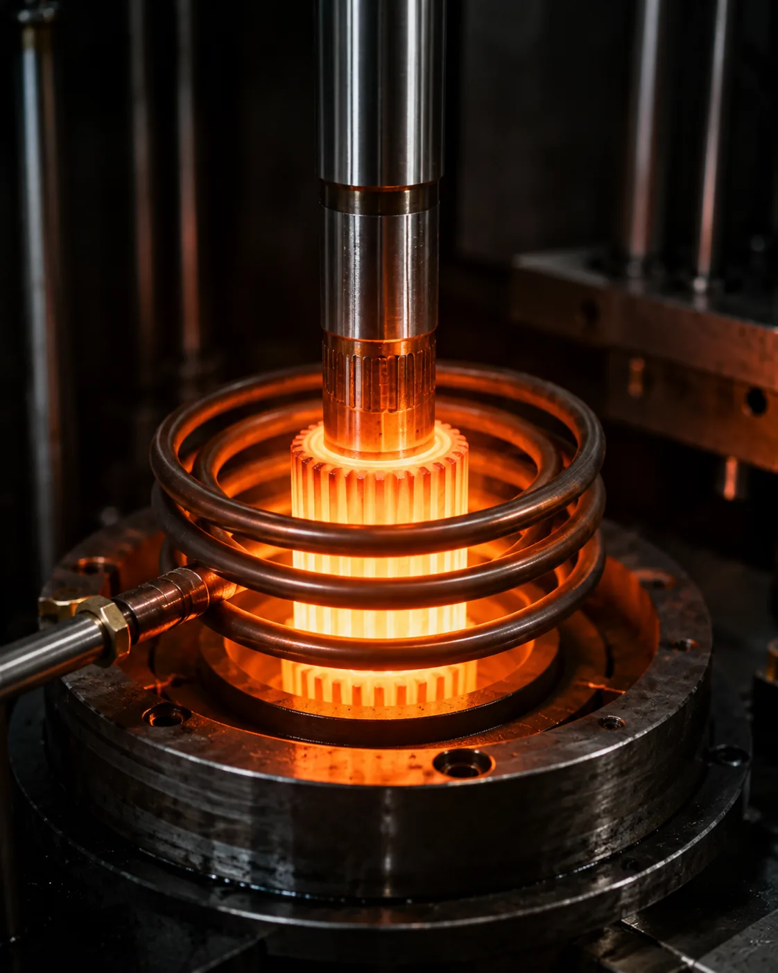
Heat treatment must be linked to the functional surface. Induction hardening can localize a hardened zone, carburizing can support a hard wear surface with a tougher core, and quench-and-temper treatment can establish a through-section strength condition before finishing. The drawing should identify where hardness applies and whether any machining or grinding follows heat treatment.
Selection variables and compatibility checks
For external spline shafts, confirm the tooth count, module or diametral pitch, pressure angle, major and minor diameters, effective engagement, total length, shoulder locations and datum references. Where a fit or accuracy class is called out, the drawing should make clear what feature and standard definition it controls. Do not infer a fit class from a product name alone; define the controlled feature and tolerance basis on the drawing.
Compatibility also depends on manufacturing and inspection access. Internal features may require broaching, shaping, wire EDM, skiving or another process depending on size and volume; external splines may be cut, milled, hobbed, rolled or ground. The best route depends on geometry, material state, quantity and accuracy requirements, so the RFQ should leave process choice open unless a qualified process is mandatory.
Manufacturing and inspection planning
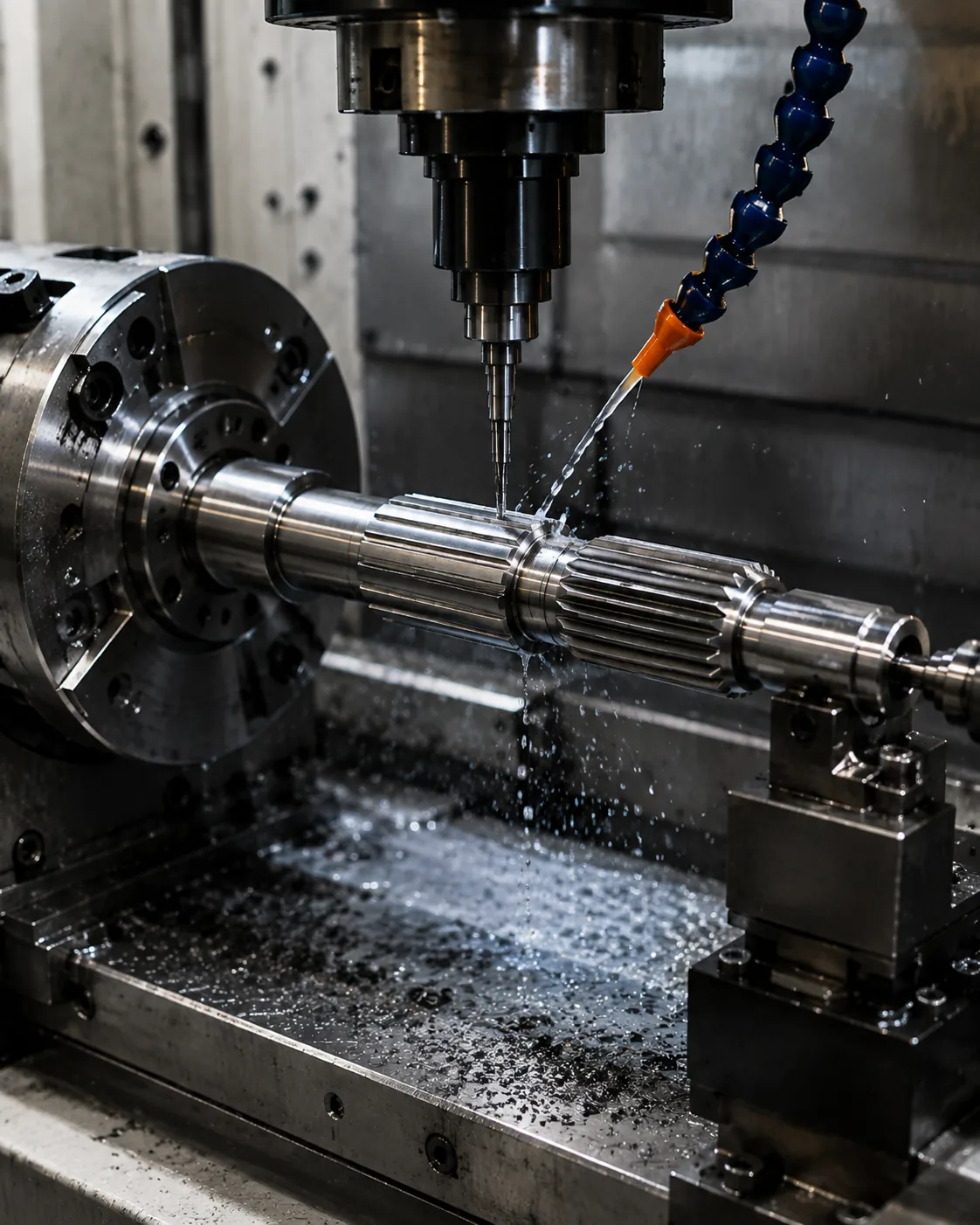
Manufacturing route should follow the geometry, material condition, quantity and required accuracy. For external spline shafts, external features may be milled, hobbed, rolled or ground, while internal features may require shaping, broaching, skiving or another qualified process. Do not force a process into the drawing unless the process itself is a functional requirement; define the finished geometry and acceptance criteria first.
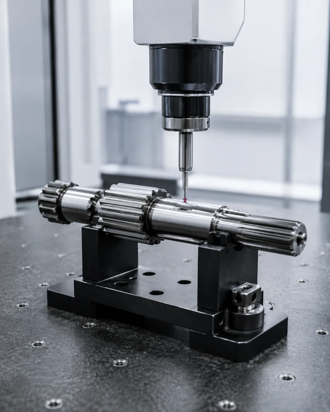
Inspection should be agreed at the same time as manufacturing planning. Gages, analytical spline measurement, CMM checks, runout inspection, surface-roughness measurement and hardness testing answer different questions. Identify which characteristics control assembly and service, then specify the corresponding measurement and report requirement. This keeps acceptance focused on function instead of a long list of unrelated checks.
How to prepare an RFQ
Include a 2D drawing and, when useful, a neutral 3D model. Mark the spline datum, mating direction, required inspection characteristics and any runout relationship to journals, gears or shoulders. State material, heat treatment, hardness range, surface finish where functional, order quantity and whether first-article inspection is required. For replacement parts, add clear photographs and explain where the original part failed or wore.
For a faster technical review, compare the available configurations in the spline shaft product range and use the spline shaft RFQ checklist to identify missing geometry before requesting a quote.
Frequently asked questions
The questions below are intended to close common specification gaps before a custom spline shaft reaches quotation or first-article production. They focus on information that can be verified on the controlled drawing: tooth geometry, mating conditions, hardness location, inspection access and the relationship between both members of the connection. When an answer depends on the actual load or fit, the correct action is to document that condition rather than apply a universal value.
Can a spline shaft be quoted from only the tooth count?
No. Tooth count alone does not define the interface. Module or pitch system, pressure angle, diameters, engagement length, fit or tolerance basis, material condition and the relationship to adjacent shaft features are also needed. For a production order, agree the inspection method and acceptance criteria before manufacture so measurement results correspond to the design requirement. Also record the mating component and revision level used for the decision, because a spline can only be judged correctly against the interface it is intended to engage. This documentation makes repeat orders and later troubleshooting much more consistent.
Should hardness be specified on the spline teeth or the whole shaft?
The drawing should say where hardness applies. Local induction hardening, carburized cases and through-section conditions are different manufacturing requirements and should not be treated as interchangeable. For a production order, agree the inspection method and acceptance criteria before manufacture so measurement results correspond to the design requirement. Also record the mating component and revision level used for the decision, because a spline can only be judged correctly against the interface it is intended to engage. This documentation makes repeat orders and later troubleshooting much more consistent.
Can an existing worn shaft be copied?
It can be used as a reference, but wear changes the geometry. The mating hub, unworn regions, datum locations and original design intent should be checked before reproducing the part. For a production order, agree the inspection method and acceptance criteria before manufacture so measurement results correspond to the design requirement. Also record the mating component and revision level used for the decision, because a spline can only be judged correctly against the interface it is intended to engage. This documentation makes repeat orders and later troubleshooting much more consistent.
Do external and internal splines use the same inspection method?
They share many geometric principles, but access and gaging differ. Internal splines often require different gage or measurement strategies from external features. For a production order, agree the inspection method and acceptance criteria before manufacture so measurement results correspond to the design requirement. Also record the mating component and revision level used for the decision, because a spline can only be judged correctly against the interface it is intended to engage. This documentation makes repeat orders and later troubleshooting much more consistent.
Does a similar-looking application guarantee compatibility?
No. Compatibility is determined by the controlled drawing, load path, mating interface and operating conditions. For a production order, agree the inspection method and acceptance criteria before manufacture so measurement results correspond to the design requirement. Also record the mating component and revision level used for the decision, because a spline can only be judged correctly against the interface it is intended to engage. This documentation makes repeat orders and later troubleshooting much more consistent.
Showing all 4 results