Comment spécifier un arbre cannelé sur mesure à partir d'un dessin Un dessin d'arbre cannelé sur mesure doit définir le système de denture en contact, les diamètres fonctionnels, l'engrènement, les références, l'état du matériau et les exigences de contrôle comme une interface unique. Commencez par le composant en contact et le chemin de charge, puis dimensionnez les éléments de l'arbre qui positionnent et supportent la cannelure afin que la fabrication et le contrôle suivent les mêmes références fonctionnelles.
Pour dessin d'arbre cannelé personnaliséLa spécification la plus fiable est celle que le concepteur, l'acheteur, le fabricant et l'inspecteur peuvent interpréter de la même manière. La discussion ci-dessous porte sur les données mesurables des plans, les conditions d'assemblage et les contrôles pratiques, plutôt que sur des affirmations universelles concernant le couple, l'ajustement ou la durée de vie, qui ne peuvent être déterminées sans données complètes sur la géométrie et le fonctionnement.
Structure de révision et de référence des dessins
Structure de révision et de référence des dessins Elle détermine la position de la cannelure par rapport aux éléments qui permettent sa rotation. Les références fonctionnelles sont généralement choisies parmi les tourillons, les diamètres de guidage, les épaulements ou autres surfaces qui positionnent le composant dans l'assemblage. La tolérance doit reproduire cette relation lors du contrôle.
Évitez d'utiliser les tolérances géométriques comme seuls indicateurs de qualité. Déterminez le défaut d'alignement admissible pour l'assemblage, identifiez le système de référence et spécifiez la caractéristique contrôlée. Le traitement thermique et la finition peuvent modifier ces valeurs ; la mesure doit donc être effectuée à l'étape de production correspondant à la pièce finie. Dans ce cas, reliez cette décision au composant d'accouplement et à la révision du dessin utilisée pour la demande de devis. Pour la section « Comment spécifier un arbre cannelé sur mesure à partir d'un dessin », appliquez cette vérification à l'interface du dessin de l'arbre cannelé sur mesure figurant sur le dessin actuel.
Système dentaire décrit
Système dentaire décrit Cette décision doit être examinée dans le contexte du dessin d'arbre cannelé sur mesure. Il convient d'identifier la pièce d'accouplement, la fonction de fonctionnement et l'élément du dessin concerné. L'exigence doit être mesurable et liée à l'ajustement, au transfert de couple, à l'alignement, à l'usure ou à tout autre besoin d'assemblage défini.
La décision doit tenir compte de l'état du matériau, de la séquence de fabrication et de l'accessibilité pour l'inspection. S'il s'agit d'une pièce de rechange, comparez la géométrie non usée et l'élément d'accouplement plutôt que de reproduire un dommage. Pour les nouvelles conceptions, privilégiez la flexibilité dans le choix des procédés, sauf si la conception elle-même impose un procédé spécifique. Dans le cadre de cette revue, le critère d'acceptation pertinent est celui qui peut être rattaché à une caractéristique fonctionnelle du dessin. Dans une demande de devis pour un dessin d'arbre cannelé sur mesure, assurez-vous que ce critère soit lié à l'élément d'accouplement, au système de référence et à la méthode d'acceptation de la pièce finie.
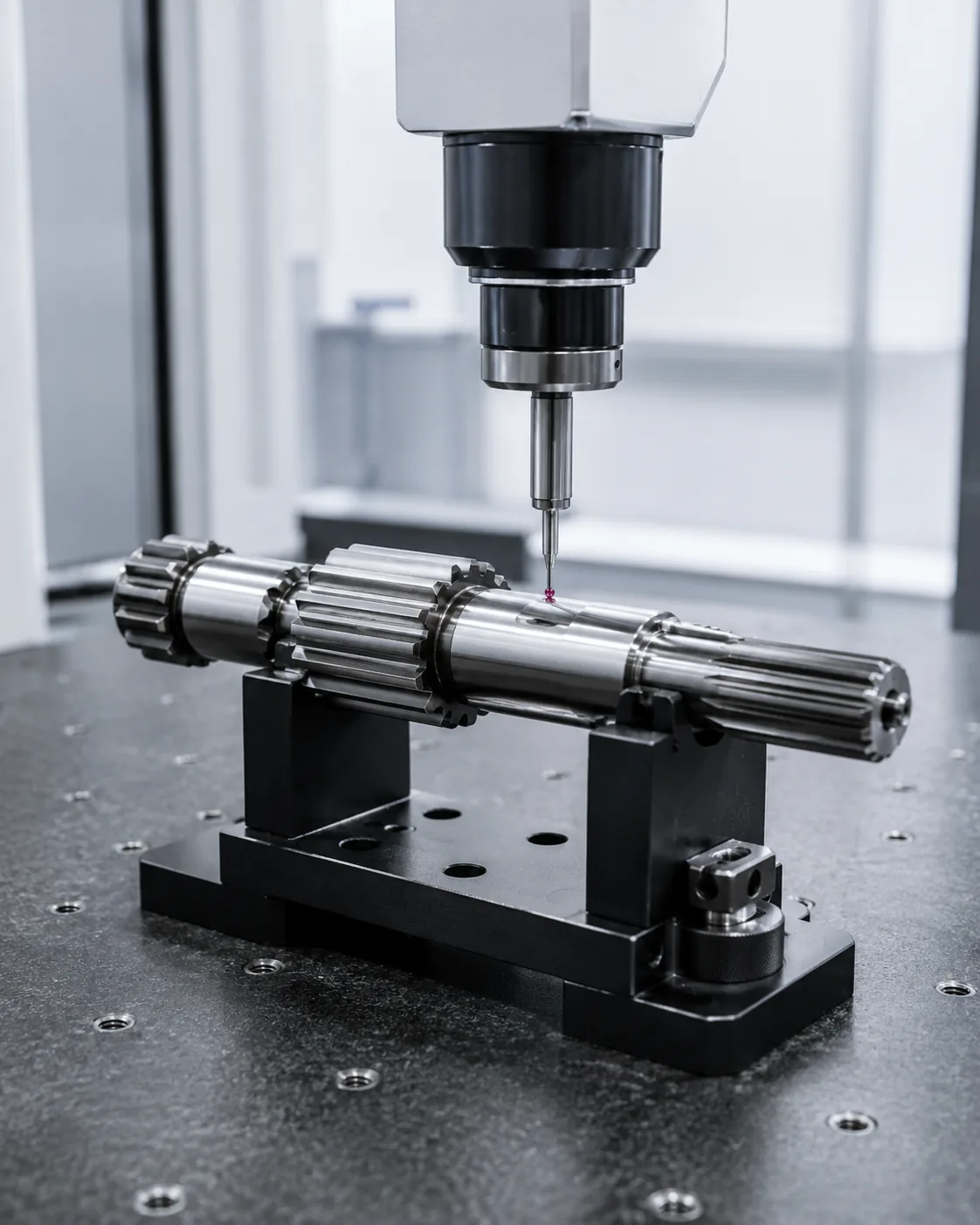
Diamètres majeur et mineur
Diamètres majeur et mineur Cette décision doit être examinée dans le contexte du dessin d'arbre cannelé sur mesure. Il convient d'identifier la pièce d'accouplement, la fonction de fonctionnement et l'élément du dessin concerné. L'exigence doit être mesurable et liée à l'ajustement, au transfert de couple, à l'alignement, à l'usure ou à tout autre besoin d'assemblage défini.
Tenez compte de l'état du matériau, de la séquence de fabrication et de l'accessibilité pour l'inspection. S'il s'agit d'une pièce de rechange, comparez la géométrie non usée et l'élément d'accouplement plutôt que de reproduire une pièce endommagée. Pour les nouvelles conceptions, privilégiez la flexibilité dans le choix des procédés, sauf si la conception l'impose. Pour les travaux répétés, conservez les mêmes références et bases de mesure, sauf si les exigences d'assemblage changent. Lors de l'examen d'un dessin d'arbre cannelé sur mesure, reprenez ce point à chaque modification du composant d'accouplement, de l'état du matériau ou des conditions de fonctionnement.
Durée d'engagement et soulagement final
Durée d'engagement et soulagement final Elle influe sur la surface de contact, la sensation d'assemblage et la répartition de la charge. L'engagement effectif correspond à la longueur sur laquelle les flancs des dents peuvent effectivement supporter la charge ; les chanfreins, les dégagements et les portions de dents incomplètes ne doivent pas être automatiquement comptabilisés dans la longueur de travail.
L'ajustement doit être évalué pour deux éléments en contact. L'épaisseur des dents, la largeur de l'espace, les jeux de diamètre, l'alignement et la température sont autant de facteurs qui influencent cet ajustement. Lors du remplacement de pièces, inspectez les deux éléments, car l'usure du moyeu peut donner l'impression qu'un arbre neuf a du jeu, même si la nouvelle cannelure externe est conforme aux tolérances du dessin. En cas de modification de la charge ou de l'élément en contact, il convient de réévaluer ce point plutôt que de se baser sur l'hypothèse précédente. Pour savoir comment spécifier un arbre cannelé sur mesure à partir d'un dessin, consignez l'exigence résultante sur le dessin ou le cahier des charges afin qu'elle reste cohérente pour les commandes ultérieures.
Définition des matériaux et des traitements thermiques
Définition des matériaux et des traitements thermiques Le choix de l'acier doit tenir compte de la charge, des dimensions de la section, du comportement au durcissement, de la résistance aux chocs, des exigences d'usure et du procédé de fabrication prévu. La nuance d'acier et le traitement thermique sont des éléments à prendre en compte conjointement ; un acier plus fortement allié n'est pas systématiquement préférable si la charge et la géométrie ne le justifient pas.
Le dessin doit indiquer la désignation du matériau requis et son état final. Si une substitution de matériau est autorisée, définissez les propriétés ou le processus d'approbation qui la régissent. Pour les arbres de diamètres multiples ou comportant des engrenages intégrés, tenez compte également de l'influence du traitement thermique sur la rectitude et la finition ultérieure. Dans ce cas, reliez cette décision à la pièce d'accouplement et à la révision du dessin utilisée pour la demande de devis. Lors de l'examen d'un dessin d'arbre cannelé sur mesure, revenez sur ce point à chaque modification de la pièce d'accouplement, de l'état du matériau ou des conditions de service.
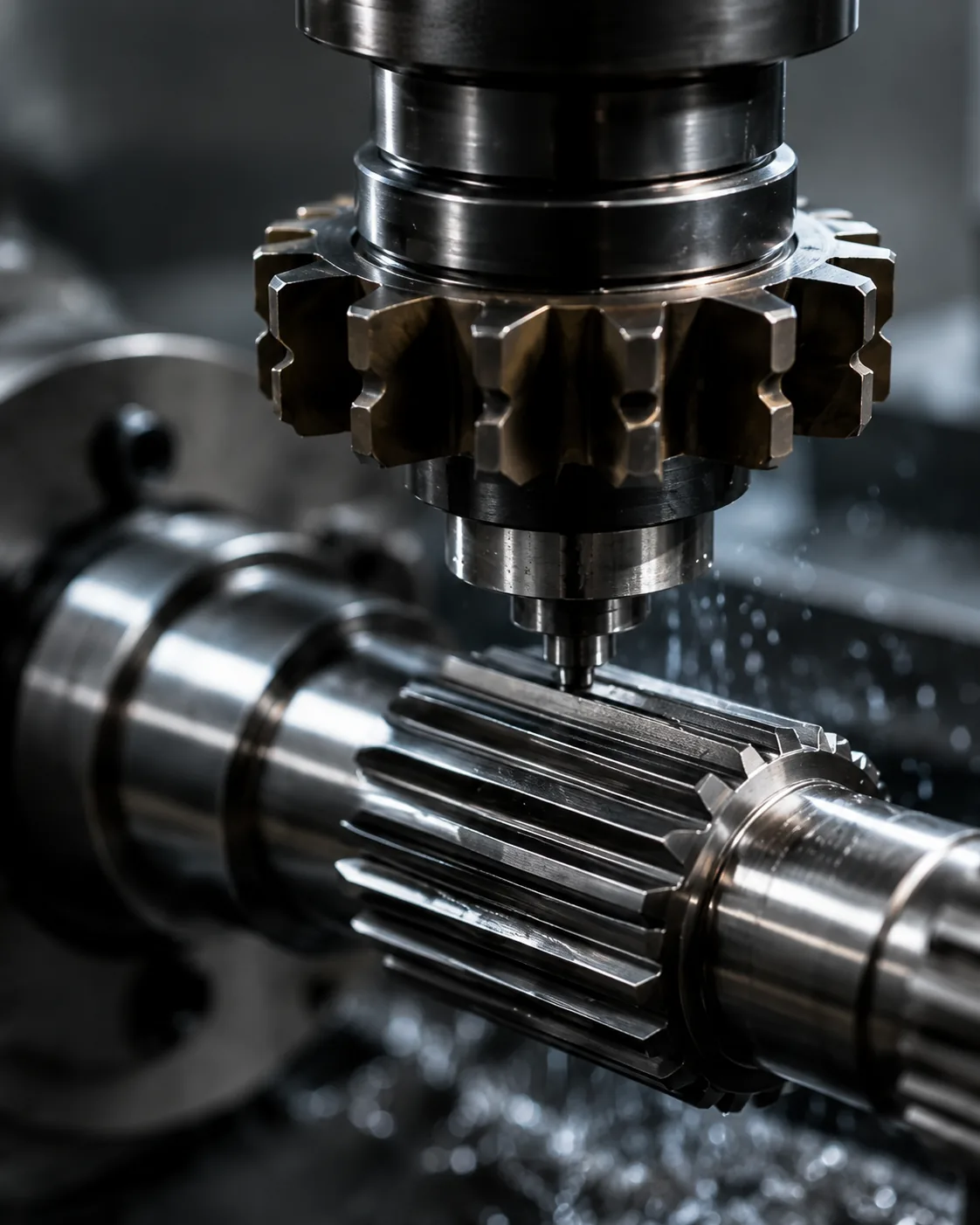
Faux-rond vers les tourillons ou les engrenages
Faux-rond vers les tourillons ou les engrenages Elle détermine la position de la cannelure par rapport aux éléments qui permettent sa rotation. Les références fonctionnelles sont généralement choisies parmi les tourillons, les diamètres de guidage, les épaulements ou autres surfaces qui positionnent le composant dans l'assemblage. La tolérance doit reproduire cette relation lors du contrôle.
Évitez d'utiliser les tolérances géométriques comme seuls indicateurs de qualité. Déterminez le désalignement admissible pour l'assemblage, identifiez le système de référence et spécifiez la caractéristique contrôlée. Le traitement thermique et la finition peuvent modifier ces relations ; la mesure doit donc être effectuée à l'étape de production représentative de la pièce finie. Dans ce contexte, le critère d'acceptation pertinent est celui qui peut être rattaché à une caractéristique fonctionnelle du dessin. Dans une demande de devis pour un dessin d'arbre cannelé sur mesure, assurez-vous que ce critère soit lié à l'élément d'accouplement, au système de référence et à la méthode d'acceptation de la pièce finie.
Une séquence de révision pratique
Une procédure de vérification pratique commence par l'identification du composant d'accouplement et du chemin de couple, puis confirme le système de denture, l'engrènement et les caractéristiques de l'arbre qui positionnent la connexion. Définissez ensuite le matériau et le traitement thermique, les finitions fonctionnelles et les exigences de faux-rond ou de position. Pour les travaux répétés, conservez les mêmes références et la même base de mesure, sauf si les exigences d'assemblage changent. Pour la spécification d'un arbre cannelé sur mesure à partir d'un dessin, consignez l'exigence résultante sur le dessin ou le cahier des charges afin qu'elle reste cohérente pour les commandes ultérieures.
Terminez en convenant de la méthode d'inspection, de la quantité et de la documentation du premier article. Cet ordre évite de prendre des décisions concernant le processus ou les tolérances avant que l'interface fonctionnelle ne soit comprise et facilite la comparaison des devis, car les mêmes données de conception sont présentées à chaque fournisseur. En cas de modification de la fonction ou de l'élément d'accouplement, revenez sur ce point au lieu de reconduire l'hypothèse précédente. Pour la spécification d'un arbre cannelé sur mesure à partir d'un dessin, consignez l'exigence résultante sur le dessin ou le cahier des charges afin qu'elle reste cohérente pour les commandes ultérieures.
Méthode d'inspection et mesure
Méthode d'inspection et mesure Il convient d'utiliser une méthode mesurant directement ou fonctionnellement la caractéristique du dessin. Les calibres fonctionnels, la mesure analytique des dents, le contrôle par machine à mesurer tridimensionnelle (MMT), les mesures d'étendue et les mesures sur broches ou billes répondent à des questions différentes et ne sont pas interchangeables par défaut.
Définissez la méthode avant la production lorsque les tolérances sont serrées ou lorsque le client et le fournisseur utilisent des équipements différents. Contrôlez la température, la propreté et l'étalonnage des instruments de mesure pour garantir la répétabilité. Le rapport d'inspection doit indiquer la révision du dessin et la configuration de référence afin que les lots ultérieurs puissent être comparés sur une base commune. À ce sujet, reliez cette décision au composant d'accouplement et à la révision du dessin utilisée pour la demande de devis. Pour la spécification d'un arbre cannelé sur mesure à partir d'un dessin, consignez l'exigence résultante sur le dessin ou le cahier des charges afin qu'elle reste cohérente pour les commandes ultérieures.
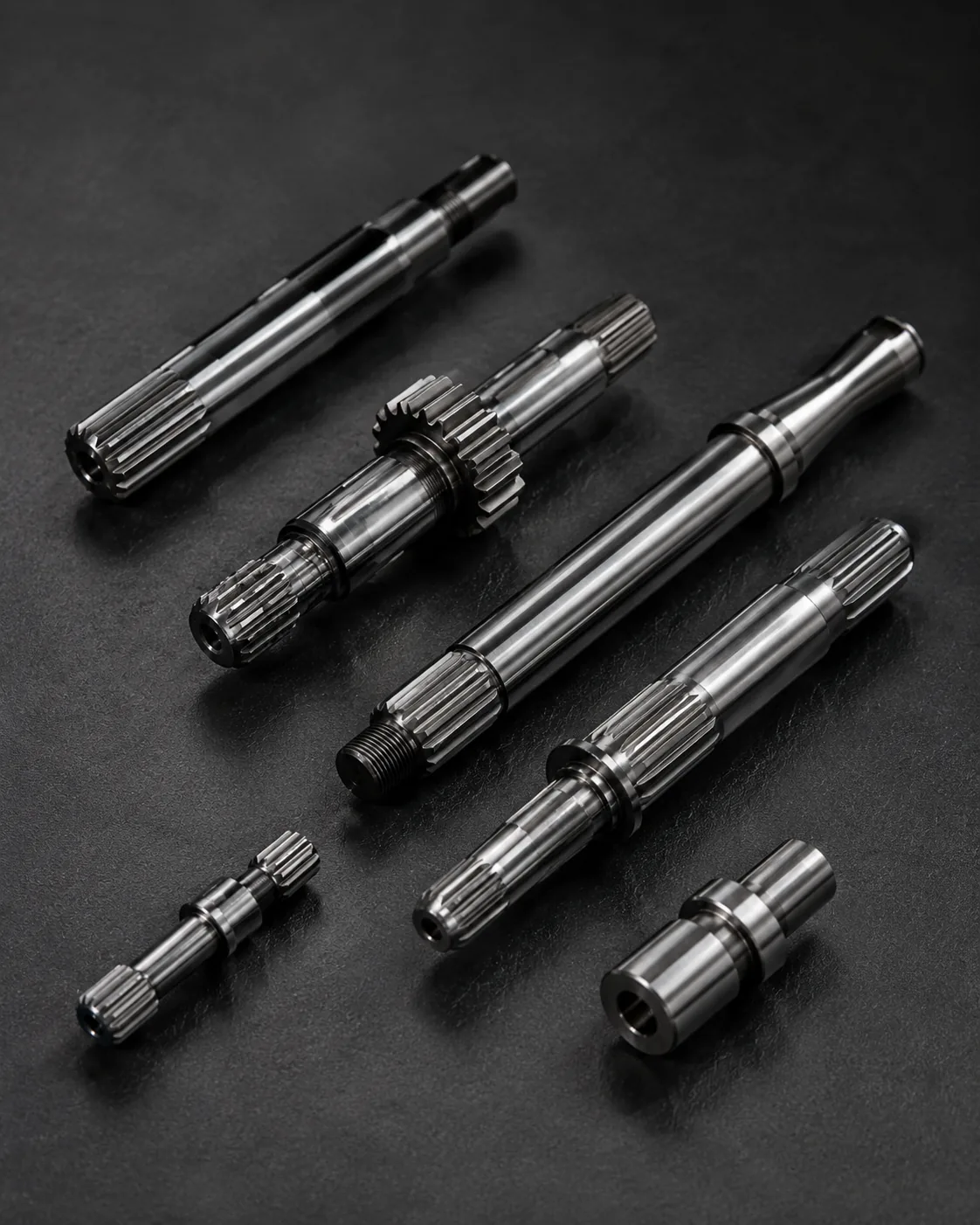
Notes relatives à la demande de devis pour les échantillons et les remplacements
Notes relatives à la demande de devis pour les échantillons et les remplacements Cette décision doit être examinée dans le contexte du dessin d'arbre cannelé sur mesure. Il convient d'identifier la pièce d'accouplement, la fonction de fonctionnement et l'élément du dessin concerné. L'exigence doit être mesurable et liée à l'ajustement, au transfert de couple, à l'alignement, à l'usure ou à tout autre besoin d'assemblage défini.
La décision doit tenir compte de l'état du matériau, de la séquence de fabrication et de l'accessibilité pour l'inspection. S'il s'agit d'une pièce de rechange, comparez la géométrie non usée et l'élément d'accouplement plutôt que de reproduire les dommages. Pour les nouvelles conceptions, privilégiez la flexibilité dans le choix des procédés, sauf si la conception l'exige. Dans cette revue, le critère d'acceptation pertinent est celui qui peut être rattaché à une caractéristique fonctionnelle du dessin. Pour la spécification d'un arbre cannelé personnalisé à partir d'un dessin, appliquez cette vérification à l'interface du dessin d'arbre cannelé personnalisé figurant sur le dessin actuel.
Erreurs courantes à éviter
Les erreurs fréquentes dans la conception d'arbres cannelés sur mesure proviennent du traitement d'une seule valeur nominale comme définissant l'interface complète. Un angle de pression manquant, des références imprécises, des cotes d'usure copiées, un emplacement de dureté non spécifié et des méthodes d'inspection inadaptées peuvent tous engendrer des pièces qui semblent correctes sur le papier, mais dont l'assemblage s'avère incohérent.
Une meilleure analyse commence par l'assemblage des pièces, identifie le chemin de charge et les points de positionnement, puis relie la géométrie, l'état des matériaux et le contrôle à ces fonctions. Clôturez les points en suspens sur le dessin avant la production et conservez l'interprétation convenue lors de la révision pour les commandes répétées. Pour les travaux répétés, conservez les mêmes références et bases de mesure, sauf si les exigences d'assemblage changent. Pour savoir comment spécifier un arbre cannelé sur mesure à partir d'un dessin, appliquez cette vérification à l'interface du dessin d'arbre cannelé sur mesure figurant sur le dessin actuel.
Résumé de la décision
| Zone de décision | Que confirmer | Pourquoi c'est important |
|---|---|---|
| Géométrie d'accouplement | Système de dents, diamètres, engagement et ajustement | Contrôle la compatibilité et le contact latéral |
| Emplacement | Références, tourillons, épaules et faux-rond | Contrôle l'alignement dans l'assemblage |
| État matériel | nuance, traitement thermique, dureté et finition | Définit l'état mécanique et d'usure final. |
| Devoir | Couple, vitesse, choc, mouvement et environnement | Relie la définition de la pièce aux conditions de fonctionnement |
| Inspection | Caractéristiques contrôlées et méthode de mesure | Garantit une acceptation cohérente entre fournisseur et acheteur |
Liste de contrôle des spécifications
- Composant d'accouplement et orientation externe/interne de la dent
- Système de module ou de pas, nombre de dents, angle de pression et diamètres majeur/mineur
- Engagement efficace, ajustement ou base de tolérance et mouvement axial si nécessaire
- Matériaux, traitement thermique, dureté et finitions de surface fonctionnelles
- Exigences relatives aux références, aux diamètres des paliers ou des pilotes, au faux-rond et à l'emplacement axial
- Couple, vitesse, choc ou charge inverse, lubrification et environnement de fonctionnement
- Quantité, exigences relatives au premier article et documentation d'inspection convenue
Utilisez le gamme de produits d'arbres cannelés pour comparer les configurations disponibles et les Liste de contrôle des dessins de la demande de prix Pour préparer une demande complète, en cas de modification de la pièce ou de l'élément d'accouplement, il convient de revenir sur ce point plutôt que de se baser sur l'hypothèse précédente. Pour savoir comment spécifier un arbre cannelé personnalisé à partir d'un dessin, appliquez cette vérification à l'interface de dessin de l'arbre cannelé personnalisé figurant sur le dessin actuel.
Fiche technique pour dessin d'arbre cannelé sur mesure
Utilisez cette feuille de travail pour tourner Comment spécifier un arbre cannelé sur mesure à partir d'un dessin en décisions pouvant être représentées sur un dessin, vérifiées lors du devis et validées à la réception de la première pièce. Commencez par Structure de révision et de référence des dessins et Système dentaire décrit, car ces deux éléments définissent généralement soit la géométrie d'assemblage, soit l'état du matériau que le reste du processus doit prendre en charge. Ensuite, examinez Diamètres majeur et mineur, Durée d'engagement et soulagement final et Définition des matériaux et des traitements thermiques contre l'assemblage réel plutôt que de les traiter comme des valeurs de catalogue indépendantes.
Pour un problème de sélection, inscrivez la pièce d'accouplement et le chemin de charge en haut de la feuille de calcul. Identifiez les surfaces sur lesquelles repose l'arbre, si la cannelure est fixe ou coulissante, le sens d'assemblage et l'engrènement effectif des dents. Notez le module ou le système de pas, le nombre de dents, l'angle de pression et les limites de diamètre à partir du dessin de référence. Si la conception est nouvelle, assurez-vous que les choix d'ajustement et de tolérance soient liés à la fonction requise ; si la pièce est un remplacement, comparez l'élément d'accouplement et les zones non usées avant de définir la géométrie nominale. Lors de la révision d'un dessin d'arbre cannelé sur mesure, revenez sur ce point chaque fois que le composant d'accouplement, l'état du matériau ou les conditions de service changent.
Ensuite, associez les diamètres majeur et mineur à la caractéristique du dessin qu'ils sont censés contrôler. Un calibre fonctionnel peut répondre à une question différente de celle posée par une mesure analytique des dents ou par une inspection CMM ; par conséquent, la demande de devis ne doit pas se limiter à une simple « inspection complète ». Précisez les caractéristiques importantes pour l'assemblage, la référence de référence utilisée et si un rapport de premier article est requis. Cela facilite la comparaison des devis des fournisseurs, car chacun examine la même définition d'interface.
séquence de révision des dessins
Avant de demander la production, examinez le dessin dans le même ordre que celui du montage : système de denture en prise, engagement effectif, références de positionnement, tourillons ou épaulements adjacents, matériau et traitement thermique, finitions fonctionnelles et méthode d’inspection. dessin d'arbre cannelé personnaliséL'ordre est important car les décisions ultérieures, telles que le choix du processus ou le choix de l'instrument de mesure, doivent soutenir l'interface plutôt que de la redéfinir.
| Élément de feuille de travail | Question à répondre | Sortie RFQ |
|---|---|---|
| Structure de révision et de référence des dessins | Quelle fonction d'assemblage cette caractéristique contrôle-t-elle ? | Référence de dimension, de tolérance ou d'accouplement |
| Système dentaire décrit | Quel état final doit être atteint ? | Spécification du matériau / du traitement thermique / de la finition |
| Diamètres majeur et mineur | Comment cette caractéristique sera-t-elle vérifiée ? | Méthode d'inspection ou note de rapport |
| Durée d'engagement et soulagement final | Comment le membre opposé s'engage-t-il ? | Informations sur les pièces d'accouplement et l'engagement |
| Définition des matériaux et des traitements thermiques | Quel référentiel établit la localisation fonctionnelle ? | Relation entre la référence et le jet-out |
Transfert de responsabilité des achats avant le premier article
Un pack d'achat utile pour Comment spécifier un arbre cannelé sur mesure à partir d'un dessin Le document contient le dessin technique, la quantité, le matériau, les conditions de traitement thermique, les informations relatives à l'interface d'assemblage et les caractéristiques de réception à signaler. Si un modèle 3D est fourni, le dessin 2D doit néanmoins comporter les tolérances, les références, les notes de traitement thermique et les exigences de contrôle. Indiquez la révision en vigueur dans la demande de devis afin d'éviter toute confusion entre les versions utilisées pour la fabrication et le contrôle.
Lorsqu'une caractéristique n'est pas encore définie, il est préférable de la signaler pour clarification technique plutôt que d'y inscrire une valeur arbitraire. Pour les dessins d'arbres cannelés sur mesure, les points en suspens concernent généralement l'engagement, l'ajustement, la dureté, le faux-rond par rapport à un tourillon adjacent, l'accès aux éléments internes ou l'état d'une pièce d'accouplement usée. La résolution de ces points avant la première production réduit les retouches inutiles et facilite le suivi des commandes ultérieures.
Liste de vérification avant la sortie
- Vérifier la révision du dessin et la structure de référence par rapport au composant d'accouplement réel.
- Confirmer le schéma du système de dents dans l'état final.
- Définir comment les diamètres majeur et mineur seront inspectés.
- Vérifier la longueur d'engagement et le dégagement d'extrémité dans les conditions d'assemblage prévues.
- Relier la définition du matériau et du traitement thermique à la structure de données fonctionnelles.
- Indiquez la quantité, le niveau de révision et toute exigence de documentation du premier article.
- Consignez les modifications apportées aux paramètres de fonctionnement, de lubrification ou de matériel d'accouplement pour les commandes répétées.
Foire aux questions
Que dois-je vérifier concernant la révision du dessin et la structure des données de référence pour le dessin d'un arbre cannelé sur mesure ?
Commencez par lier la révision du dessin et la structure de référence au composant d'accouplement et à la fonction d'assemblage. Indiquez l'exigence mesurable sur le dessin de référence et incluez l'élément opposé lorsque la compatibilité dépend des deux pièces. Pour la spécification d'un arbre cannelé sur mesure à partir d'un dessin, cela évite qu'une étiquette nominale ne remplace la géométrie qui détermine réellement l'ajustement et le transfert de couple.
Que dois-je vérifier concernant le schéma du système de denture pour un arbre cannelé sur mesure ?
Confirmer la spécification du système de denture à l'état fini, en précisant tout matériau, traitement thermique, état de surface ou dimensionnel susceptible d'évoluer après usinage. Si la spécification dépend d'un emplacement ou d'une référence, l'indiquer explicitement afin que la production et le contrôle utilisent la même référence.
Que dois-je vérifier concernant les diamètres majeur et mineur pour le dessin d'un arbre cannelé sur mesure ?
Choisissez une méthode d'inspection permettant de mesurer la caractéristique mentionnée sur le dessin. Les mesures fonctionnelles, les mesures analytiques des cannelures, les contrôles par machine à mesurer tridimensionnelle (MMT), le contrôle du faux-rond, la mesure de la rugosité et les essais de dureté répondent à des questions différentes. Précisez le résultat requis pour la réception plutôt que de demander un rapport d'inspection générique. Lors de l'examen d'un dessin d'arbre cannelé sur mesure, revenez sur ce point à chaque modification de la pièce d'accouplement, de l'état du matériau ou des conditions de service.
Que dois-je vérifier concernant la longueur d'engagement et le dégagement d'extrémité pour le dessin d'un arbre cannelé sur mesure ?
Vérifiez la longueur d'engagement et le dégagement d'extrémité avec la pièce d'accouplement réelle et dans les conditions d'assemblage prévues. L'engagement effectif, le jeu, le mouvement axial, la température et l'usure d'un moyeu de remplacement peuvent tous influencer le comportement de la liaison. Un arbre neuf ne doit pas être accepté ou rejeté uniquement au toucher lorsqu'une exigence d'ajustement mesurable est disponible.
Que dois-je vérifier concernant la définition du matériau et du traitement thermique pour le dessin d'un arbre cannelé sur mesure ?
Associez les définitions du matériau et du traitement thermique aux éléments qui déterminent la rotation dans l'assemblage. Le dessin doit clairement indiquer la référence de base et tout faux-rond ou relation de position. Si le traitement thermique ou l'usinage de finition peut modifier l'élément, vérifiez la relation à l'étape correspondant à la pièce finie.
De la décision d'ingénierie au contrôle de la production
Une fois l'interface validée, traduisez chaque décision fonctionnelle en une caractéristique de dessin exploitable pour la fabrication et le contrôle. Évitez de laisser les relations clés uniquement dans des notes de courriel. Les dimensions, les références, les conditions de traitement thermique et les critères d'acceptation doivent faire l'objet d'un suivi des révisions afin que les équipes de production et de contrôle travaillent selon la même définition. Pour les travaux répétitifs, conservez les mêmes références et bases de mesure, sauf en cas de modification des exigences d'assemblage. Pour savoir comment spécifier un arbre cannelé sur mesure à partir d'un dessin, appliquez cette vérification à l'interface de dessin de l'arbre cannelé sur mesure figurant sur le dessin actuel.
Pour les premières pièces, privilégiez les caractéristiques garantissant la compatibilité d'assemblage : géométrie des dents, ajustement précis, relation avec les tourillons ou épaulements de positionnement, état du traitement thermique et tout faux-rond critique. Consignez la méthode de mesure ainsi que le résultat. Pour les commandes répétées, l'utilisation d'une même configuration de référence et d'une même méthode de mesure facilite la détection des évolutions et réduit les litiges liés à des interprétations différentes lors des contrôles. En cas de modification de la pièce ou de l'élément d'accouplement, réexaminez ce point au lieu de vous baser sur l'hypothèse précédente. Dans une demande de devis pour un dessin d'arbre cannelé sur mesure, assurez-vous que ce point soit lié à l'élément d'accouplement, au système de référence et à la méthode de réception de la pièce finie.
En cas de modification des conditions de fonctionnement, il convient de reprendre l'étude technique au lieu de considérer que les spécifications précédentes restent appropriées. Un couple plus élevé, des chocs accrus, des inversions de sens plus fréquentes, une lubrification différente ou un nouveau composant d'accouplement peuvent modifier le contact et l'usure, même si le diamètre nominal de la cannelure demeure inchangé. Le dessin doit évoluer en fonction des exigences d'assemblage réelles. Dans ce cas, il est important de relier cette décision au composant d'accouplement et à la révision du dessin utilisée pour la demande de devis. Lors de l'examen d'un dessin d'arbre cannelé sur mesure, il est nécessaire de revenir sur ce point à chaque modification du composant d'accouplement, de l'état du matériau ou des conditions de fonctionnement.
Préparer la demande de prix
- Dessin 2D actuel et révision
- Définition des composants d'accouplement et de la spline
- Matériaux, traitement thermique et finitions fonctionnelles
- Couple, vitesse, rapport cyclique et environnement
- Quantité et documentation d'inspection requise
Une demande de renseignements complète combine le dessin, l'interface d'assemblage, l'état du matériau, la charge, la quantité et les exigences d'inspection. Lorsque ces éléments sont définis en amont, les fournisseurs peuvent planifier l'outillage, le traitement thermique, la finition et les mesures en fonction de l'exigence fonctionnelle, réduisant ainsi les cycles de clarification avant la production du premier article. Dans cette revue, le critère d'acceptation pertinent est celui qui peut être rattaché à une caractéristique fonctionnelle du dessin. Pour savoir comment spécifier un arbre cannelé sur mesure à partir d'un dessin, appliquez cette vérification à l'interface du dessin de l'arbre cannelé sur mesure figurant sur le dessin actuel.
Transformez le guide en demande de devis.
Veuillez envoyer le dessin technique, l'interface d'accouplement, les informations relatives à l'état du matériau et aux fonctions pour examen technique.
Demander un devis