Condition: New Guarantee: 1 Year Applicable Industries: Other Showroom Place: None Video outgoing-inspection: Supplied Equipment Take a look at Report: Offered Advertising Kind: Normal Item Warranty of main parts: 1 12 months Main Parts: Motor, Gear Composition: Spline Materials: Stainless Steel, Carbon Steel, Aluminum Coatings: Black Oxide, Nickel And so on Torque Capacity: Customers’requirements Design Variety: LP056 Solution identify: Precision Universal CNC Hex Eccentric Threaded Bearing Clamp Shaft OEM & ODM: Offered/welcome Application: Car, Motor, Circular Observed Etc Approach: CNC Turning Machining+Car Lathe Diameter: 2~210MM Merchandise Identify: CNC Hex Shaft Good quality Management: 100% Inspection Before Cargo Drawing documents: CAD/UG/PROE and so forth Tolerance: .003mm~.01mm Certification: ISO9001:2008 Right after Warranty Service: On-line support Neighborhood Service Location: None Packaging Particulars: Packing: Plastic baggage for within packing small customized-produced cartons for within packing massive tough carton for outdoors packing pallet packing for shipping or as for each your demands. Port: HangZhou Port
L/C, T/T, China Manufacturer Tiny Worm Gearbox NRV40 Escow, Paypal, Western Union, Income
Top quality manage
RoHS tester , callipers , salt spary tester , 3D coordonate measuring instrument
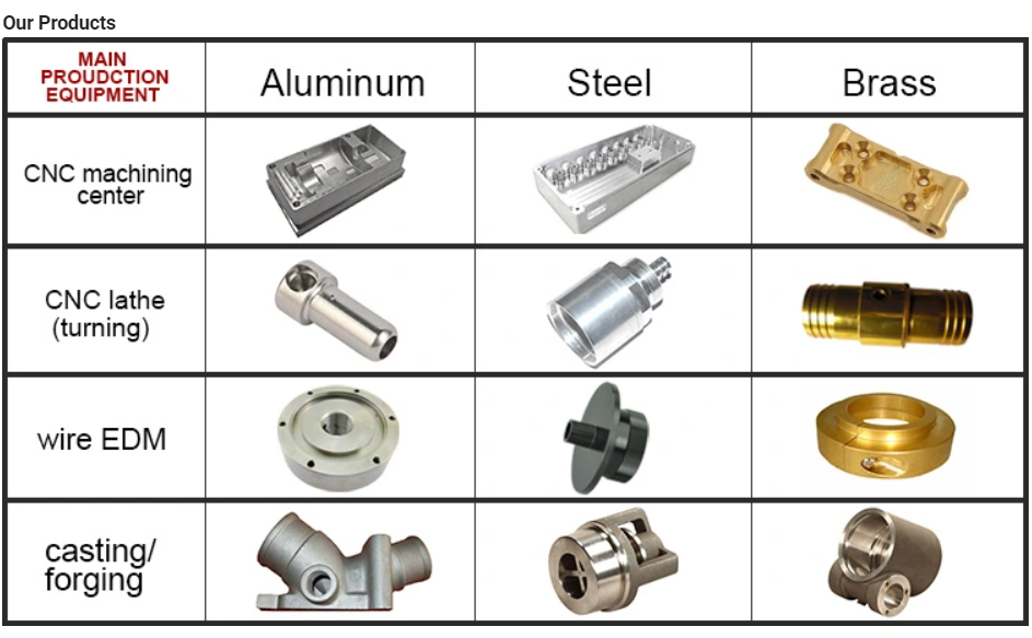
Machines/tools
Stamping machines 30 sets (2 tonnage – three hundred tonnage) ,CNC middle machins 5 sets automatic lathe turning areas fifty sets (The processing diameter is significantly less than 22mm) , electrical contact rivets devices 100 sets, rivets devices 30 sets , spring equipment ten sets
Other Services
OEM &OEM, Personalized Specification, 1 to One particular Communication, Cost-free Samples
Additional
1)Sample Order and Tiny Get are suitable 2)The strategies of shipping: DHL, Big new motocross path 4 stroke pit bike 300cc filth bicycle low cost petrol off road motorcycle from china EMS,UPS or Fedex (rapidly and safer) 3)Located in producing foundation of china-HangZhou metropolis,we also aid buyer design and style in accordance to customers’ needs and products’ software.
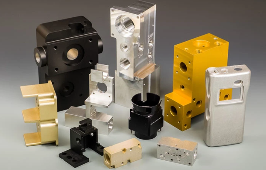
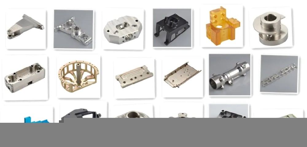
Product photo:
Make sure you Simply click “Contact US” To Location An Get If You Are Fascinated In Our Merchandise!!! Packing About Us Comment from Buyers: FAQ one.Are you a trade organization or a producer? A:We are a manufacturer specialised in hardware fittings creation for a lot more than 20 years, main goods consist of cnc machining elements,metal stamping elements,rivets,aluminum profile, electrical get in touch with etc,we offer OEM & ODM support.
two.What is your delivery day? A:The shipping and delivery date is fifteen~twenty days right after receipt of payment.
3.How is the content utilised for your solution? A:The content we employed for our solution is environmental & protected.
4.What is your payment phrases? A:30%~fifty% deposit,the equilibrium ahead of shipment.
five.How is the top quality of your product? A:100% good quality inspection just before shipment,the detect fee is less than .7%. Contact us OUR Main Goods:
CNC Turning Components
CNC Milling Components
Aluminum Profile CNC Machining
Lathe Areas
Back TO HOME–> a hundred% Motorcycle Carbon Fiber Material Fairing Kits Chain Sprocket Swingarm Elements For KTM DUKE 690 2008-2019 >>
Stiffness and Torsional Vibration of Spline-Couplings
In this paper, we describe some basic characteristics of spline-coupling and examine its torsional vibration behavior. We also explore the effect of spline misalignment on rotor-spline coupling. These results will assist in the design of improved spline-coupling systems for various applications. The results are presented in Table 1.
Stiffness of spline-coupling
The stiffness of a spline-coupling is a function of the meshing force between the splines in a rotor-spline coupling system and the static vibration displacement. The meshing force depends on the coupling parameters such as the transmitting torque and the spline thickness. It increases nonlinearly with the spline thickness. A simplified spline-coupling model can be used to evaluate the load distribution of splines under vibration and transient loads. The axle spline sleeve is displaced a z-direction and a resistance moment T is applied to the outer face of the sleeve. This simple model can satisfy a wide range of engineering requirements but may suffer from complex loading conditions. Its asymmetric clearance may affect its engagement behavior and stress distribution patterns. The results of the simulations show that the maximum vibration acceleration in both Figures 10 and 22 was 3.03 g/s. This results indicate that a misalignment in the circumferential direction increases the instantaneous impact. Asymmetry in the coupling geometry is also found in the meshing. The right-side spline’s teeth mesh tightly while those on the left side are misaligned. Considering the spline-coupling geometry, a semi-analytical model is used to compute stiffness. This model is a simplified form of a classical spline-coupling model, with submatrices defining the shape and stiffness of the joint. As the design clearance is a known value, the stiffness of a spline-coupling system can be analyzed using the same formula. The results of the simulations also show that the spline-coupling system can be modeled using MASTA, a high-level commercial CAE tool for transmission analysis. In this case, the spline segments were modeled as a series of spline segments with variable stiffness, which was calculated based on the initial gap between spline teeth. Then, the spline segments were modelled as a series of splines of increasing stiffness, accounting for different manufacturing variations. The resulting analysis of the spline-coupling geometry is compared to those of the finite-element approach. Despite the high stiffness of a spline-coupling system, the contact status of the contact surfaces often changes. In addition, spline coupling affects the lateral vibration and deformation of the rotor. However, stiffness nonlinearity is not well studied in splined rotors because of the lack of a fully analytical model.
Characteristics of spline-coupling
The study of spline-coupling involves a number of design factors. These include weight, materials, and performance requirements. Weight is particularly important in the aeronautics field. Weight is often an issue for design engineers because materials have varying dimensional stability, weight, and durability. Additionally, space constraints and other configuration restrictions may require the use of spline-couplings in certain applications. The main parameters to consider for any spline-coupling design are the maximum principal stress, the maldistribution factor, and the maximum tooth-bearing stress. The magnitude of each of these parameters must be smaller than or equal to the external spline diameter, in order to provide stability. The outer diameter of the spline must be at least four inches larger than the inner diameter of the spline. Once the physical design is validated, the spline coupling knowledge base is created. This model is pre-programmed and stores the design parameter signals, including performance and manufacturing constraints. It then compares the parameter values to the design rule signals, and constructs a geometric representation of the spline coupling. A visual model is created from the input signals, and can be manipulated by changing different parameters and specifications. The stiffness of a spline joint is another important parameter for determining the spline-coupling stiffness. The stiffness distribution of the spline joint affects the rotor’s lateral vibration and deformation. A finite element method is a useful technique for obtaining lateral stiffness of spline joints. This method involves many mesh refinements and requires a high computational cost. The diameter of the spline-coupling must be large enough to transmit the torque. A spline with a larger diameter may have greater torque-transmitting capacity because it has a smaller circumference. However, the larger diameter of a spline is thinner than the shaft, and the latter may be more suitable if the torque is spread over a greater number of teeth. Spline-couplings are classified according to their tooth profile along the axial and radial directions. The radial and axial tooth profiles affect the component’s behavior and wear damage. Splines with a crowned tooth profile are prone to angular misalignment. Typically, these spline-couplings are oversized to ensure durability and safety.
Stiffness of spline-coupling in torsional vibration analysis
This article presents a general framework for the study of torsional vibration caused by the stiffness of spline-couplings in aero-engines. It is based on a previous study on spline-couplings. It is characterized by the following three factors: bending stiffness, total flexibility, and tangential stiffness. The first criterion is the equivalent diameter of external and internal splines. Both the spline-coupling stiffness and the displacement of splines are evaluated by using the derivative of the total flexibility. The stiffness of a spline joint can vary based on the distribution of load along the spline. Variables affecting the stiffness of spline joints include the torque level, tooth indexing errors, and misalignment. To explore the effects of these variables, an analytical formula is developed. The method is applicable for various kinds of spline joints, such as splines with multiple components. Despite the difficulty of calculating spline-coupling stiffness, it is possible to model the contact between the teeth of the shaft and the hub using an analytical approach. This approach helps in determining key magnitudes of coupling operation such as contact peak pressures, reaction moments, and angular momentum. This approach allows for accurate results for spline-couplings and is suitable for both torsional vibration and structural vibration analysis. The stiffness of spline-coupling is commonly assumed to be rigid in dynamic models. However, various dynamic phenomena associated with spline joints must be captured in high-fidelity drivetrain models. To accomplish this, a general analytical stiffness formulation is proposed based on a semi-analytical spline load distribution model. The resulting stiffness matrix contains radial and tilting stiffness values as well as torsional stiffness. The analysis is further simplified with the blockwise inversion method. It is essential to consider the torsional vibration of a power transmission system before selecting the coupling. An accurate analysis of torsional vibration is crucial for coupling safety. This article also discusses case studies of spline shaft wear and torsionally-induced failures. The discussion will conclude with the development of a robust and efficient method to simulate these problems in real-life scenarios.
Effect of spline misalignment on rotor-spline coupling
In this study, the effect of spline misalignment in rotor-spline coupling is investigated. The stability boundary and mechanism of rotor instability are analyzed. We find that the meshing force of a misaligned spline coupling increases nonlinearly with spline thickness. The results demonstrate that the misalignment is responsible for the instability of the rotor-spline coupling system. An intentional spline misalignment is introduced to achieve an interference fit and zero backlash condition. This leads to uneven load distribution among the spline teeth. A further spline misalignment of 50um can result in rotor-spline coupling failure. The maximum tensile root stress shifted to the left under this condition. Positive spline misalignment increases the gear mesh misalignment. Conversely, negative spline misalignment has no effect. The right-handed spline misalignment is opposite to the helix hand. The high contact area is moved from the center to the left side. In both cases, gear mesh is misaligned due to deflection and tilting of the gear under load. This variation of the tooth surface is measured as the change in clearance in the transverse plain. The radial and axial clearance values are the same, while the difference between the two is less. In addition to the frictional force, the axial clearance of the splines is the same, which increases the gear mesh misalignment. Hence, the same procedure can be used to determine the frictional force of a rotor-spline coupling. Gear mesh misalignment influences spline-rotor coupling performance. This misalignment changes the distribution of the gear mesh and alters contact and bending stresses. Therefore, it is essential to understand the effects of misalignment in spline couplings. Using a simplified system of helical gear pair, Hong et al. examined the load distribution along the tooth interface of the spline. This misalignment caused the flank contact pattern to change. The misaligned teeth exhibited deflection under load and developed a tilting moment on the gear. The effect of spline misalignment in rotor-spline couplings is minimized by using a mechanism that reduces backlash. The mechanism comprises cooperably splined male and female members. One member is formed by two coaxially aligned splined segments with end surfaces shaped to engage in sliding relationship. The connecting device applies axial loads to these segments, causing them to rotate relative to one another.
Condition: New Warranty: Much more than 5 years Relevant Industries: Constructing Substance Retailers, Producing Plant, Machinery Restore Outlets, Foods & Beverage Factory, Printing Outlets, Building works , Vitality & Mining Showroom Place: None Video clip outgoing-inspection: Presented Equipment Check Report: Offered Marketing and advertising Variety: New Item 2571 Warranty of core components: A lot more than 5 many years Core Elements: other Construction: Spline Content: Alloy steel Coatings: Other Torque Potential: 33K N.m Model Variety: GJF20 Item identify: Ball Spline Accuracy Quality: 2/3/4 Nominal axial diameter: 16-a hundred and fifty Torsion clearance: P0/P1/P2 Static load: 8.1-221.3KN Exterior diameter: 23-135 Oil gap: 2-5 Place of oil hole: 13-55 Depth of counter bore: 4.4-17.5 Top quality: Large Precision After Warranty Services: Movie technological assistance, On the internet assistance, Spare areas, Discipline maintenance and mend support Nearby Service Location: None Packaging Specifics: Paper and wood box for 8.1-221.3KN static load 16-one hundred fifty nominal axial diameter shaft bearing prolonged steel spline shaft Port: ZheJiang
Item Overview Precision linear motion spline seriesThe spline is a kind of linear motion method. When spline motions along the precision floor Shaft by balls, the torque is transferred. The spline has compact construction. It can transfer the Over load and motive power. It has more time life time.At current the manufacturing facility manufacture 2 kinds of spline, namely convex spline and concave spline. Normally the convex spline can get larger radial load and torque than concave spline. Attributes AT A Look Ball sort:φ Large Torque Aluminum Substance Worm Gearbox RV Collection Worm Equipment Box with Output Flange Gear Box 16-φ250High speed , large accuracyHeavy load , prolonged lifeFlexible movement,reduced power consumptionHigh movement speedHeavy load and long provider lifeApplicationgs:semiconductor equipment,tire machinery,monocrystalline silicon furnace,health-related rehabilitation tools Solution Specifications
Xihu (West Lake) Dis.ye 40 many years Knowledgeable Manufacturing unit Manufactured 50Mm 12V 24V Worm Gearbox with Motor for Intelligent Home Appliance 02 -.3
+.12.50
+.230
+.230
+.240
Length of slot grooveI
20
26
36
26
40
Oil holed
2
3
3
3
3
Dynamic torsionN-m
38.nine
100
152.
192.2
288.nine
Stationary torsionN-m
105.9
270.five
345.
425.8
613.two
Dynamic loadC KN
5.5
10.719
13
16.3
19.three
Static loadC KN
13.three
25.499
26
33.one
36.one
GJZA Convex sort
Spec.
GJZA40
GJZA50
GJZA60
GJZA70
GJZA85
GJZA100
GJZA120
GJZA150
Nominal axial dia. d0
40
50
60
70
85
100
120
150
External dia.D
060-.019
075-.019
090-.571
5710-.571
0120-.571
0140-.571
0160-.571
5715-.571
Length of spline nut L1
5710-.three
0112-.3
0127-.three
0135-.three
0155-.three
0175-.4
5710-.four
5710-.four
Max. duration of shaft L
1500
1500
1500
1700
1900
1900
1900
1900
Width of slot groove b
10H8
14H8
16H8
18H8
20H8
28H8
28H8
32H8
Depth of slot groove t
+.250
+.twenty five.50
+.260
+.160
+.one hundred seventy
+.a hundred ninety
+.one hundred ninety
+.1100
Length of slot groove I
56
60
70
68
80
93
123
157
Oil hole d
4
4
4
4
5
5
6
6
Bike Chain Washer Cleansing Brush Chain Crank Sprocket Double-Sides Cleansing Washing Brushes Deal with Dynamic torsion N-m
651.nine
1048.
2135.9
3153.four
4437.two
6943.8
10153.5
19564.1
Stationary torsion N-m
1390.9
2200.7
4172.9
5797.six
8082.
11737.two
18779.5
33532.7
Dynamic load C KN
34.nine
44.nine
76.2
96.5
111.8
148.seven
181.three
279.four
Static load C0 KN
65.5
82.nine
131.one
156.1
179.2
221.3
295
421.5
Manufacturing Tools 4m CNC linear CZPT grinding device straightening&quenching equipment Gap- punching equipment Income AND Support Network Equivalent Goods Effective Venture SYMG CZPT DMTG
How to Calculate Stiffness, Centering Force, Wear and Fatigue Failure of Spline Couplings
There are various types of spline couplings. These couplings have several important properties. These properties are: Stiffness, Involute splines, Misalignment, Wear and fatigue failure. To understand how these characteristics relate to spline couplings, read this article. It will give you the necessary knowledge to determine which type of coupling best suits your needs. Keeping in mind that spline couplings are usually spherical in shape, they are made of steel.
Involute splines
An effective side interference condition minimizes gear misalignment. When two splines are coupled with no spline misalignment, the maximum tensile root stress shifts to the left by five mm. A linear lead variation, which results from multiple connections along the length of the spline contact, increases the effective clearance or interference by a given percentage. This type of misalignment is undesirable for coupling high-speed equipment. Involute splines are often used in gearboxes. These splines transmit high torque, and are better able to distribute load among multiple teeth throughout the coupling circumference. The involute profile and lead errors are related to the spacing between spline teeth and keyways. For coupling applications, industry practices use splines with 25 to fifty-percent of spline teeth engaged. This load distribution is more uniform than that of conventional single-key couplings. To determine the optimal tooth engagement for an involved spline coupling, Xiangzhen Xue and colleagues used a computer model to simulate the stress applied to the splines. The results from this study showed that a “permissible” Ruiz parameter should be used in coupling. By predicting the amount of wear and tear on a crowned spline, the researchers could accurately predict how much damage the components will sustain during the coupling process. There are several ways to determine the optimal pressure angle for an involute spline. Involute splines are commonly measured using a pressure angle of 30 degrees. Similar to gears, involute splines are typically tested through a measurement over pins. This involves inserting specific-sized wires between gear teeth and measuring the distance between them. This method can tell whether the gear has a proper tooth profile. The spline system shown in Figure 1 illustrates a vibration model. This simulation allows the user to understand how involute splines are used in coupling. The vibration model shows four concentrated mass blocks that represent the prime mover, the internal spline, and the load. It is important to note that the meshing deformation function represents the forces acting on these three components.
Stiffness of coupling
The calculation of stiffness of a spline coupling involves the measurement of its tooth engagement. In the following, we analyze the stiffness of a spline coupling with various types of teeth using two different methods. Direct inversion and blockwise inversion both reduce CPU time for stiffness calculation. However, they require evaluation submatrices. Here, we discuss the differences between these two methods. The analytical model for spline couplings is derived in the second section. In the third section, the calculation process is explained in detail. We then validate this model against the FE method. Finally, we discuss the influence of stiffness nonlinearity on the rotor dynamics. Finally, we discuss the advantages and disadvantages of each method. We present a simple yet effective method for estimating the lateral stiffness of spline couplings. The numerical calculation of the spline coupling is based on the semi-analytical spline load distribution model. This method involves refined contact grids and updating the compliance matrix at each iteration. Hence, it consumes significant computational time. Further, it is difficult to apply this method to the dynamic analysis of a rotor. This method has its own limitations and should be used only when the spline coupling is fully investigated. The meshing force is the force generated by a misaligned spline coupling. It is related to the spline thickness and the transmitting torque of the rotor. The meshing force is also related to the dynamic vibration displacement. The result obtained from the meshing force analysis is given in Figures 7, 8, and 9. The analysis presented in this paper aims to investigate the stiffness of spline couplings with a misaligned spline. Although the results of previous studies were accurate, some issues remained. For example, the misalignment of the spline may cause contact damages. The aim of this article is to investigate the problems associated with misaligned spline couplings and propose an analytical approach for estimating the contact pressure in a spline connection. We also compare our results to those obtained by pure numerical approaches.
Misalignment
To determine the centering force, the effective pressure angle must be known. Using the effective pressure angle, the centering force is calculated based on the maximum axial and radial loads and updated Dudley misalignment factors. The centering force is the maximum axial force that can be transmitted by friction. Several published misalignment factors are also included in the calculation. A new method is presented in this paper that considers the cam effect in the normal force. In this new method, the stiffness along the spline joint can be integrated to obtain a global stiffness that is applicable to torsional vibration analysis. The stiffness of bearings can also be calculated at given levels of misalignment, allowing for accurate estimation of bearing dimensions. It is advisable to check the stiffness of bearings at all times to ensure that they are properly sized and aligned. A misalignment in a spline coupling can result in wear or even failure. This is caused by an incorrectly aligned pitch profile. This problem is often overlooked, as the teeth are in contact throughout the involute profile. This causes the load to not be evenly distributed along the contact line. Consequently, it is important to consider the effect of misalignment on the contact force on the teeth of the spline coupling. The centre of the male spline in Figure 2 is superposed on the female spline. The alignment meshing distances are also identical. Hence, the meshing force curves will change according to the dynamic vibration displacement. It is necessary to know the parameters of a spline coupling before implementing it. In this paper, the model for misalignment is presented for spline couplings and the related parameters. Using a self-made spline coupling test rig, the effects of misalignment on a spline coupling are studied. In contrast to the typical spline coupling, misalignment in a spline coupling causes fretting wear at a specific position on the tooth surface. This is a leading cause of failure in these types of couplings.
Wear and fatigue failure
The failure of a spline coupling due to wear and fatigue is determined by the first occurrence of tooth wear and shaft misalignment. Standard design methods do not account for wear damage and assess the fatigue life with big approximations. Experimental investigations have been conducted to assess wear and fatigue damage in spline couplings. The tests were conducted on a dedicated test rig and special device connected to a standard fatigue machine. The working parameters such as torque, misalignment angle, and axial distance have been varied in order to measure fatigue damage. Over dimensioning has also been assessed. During fatigue and wear, mechanical sliding takes place between the external and internal splines and results in catastrophic failure. The lack of literature on the wear and fatigue of spline couplings in aero-engines may be due to the lack of data on the coupling’s application. Wear and fatigue failure in splines depends on a number of factors, including the material pair, geometry, and lubrication conditions. The analysis of spline couplings shows that over-dimensioning is common and leads to different damages in the system. Some of the major damages are wear, fretting, corrosion, and teeth fatigue. Noise problems have also been observed in industrial settings. However, it is difficult to evaluate the contact behavior of spline couplings, and numerical simulations are often hampered by the use of specific codes and the boundary element method. The failure of a spline gear coupling was caused by fatigue, and the fracture initiated at the bottom corner radius of the keyway. The keyway and splines had been overloaded beyond their yield strength, and significant yielding was observed in the spline gear teeth. A fracture ring of non-standard alloy steel exhibited a sharp corner radius, which was a significant stress raiser. Several components were studied to determine their life span. These components include the spline shaft, the sealing bolt, and the graphite ring. Each of these components has its own set of design parameters. However, there are similarities in the distributions of these components. Wear and fatigue failure of spline couplings can be attributed to a combination of the three factors. A failure mode is often defined as a non-linear distribution of stresses and strains.
21618-Travel SHAFT 30% T/T in advance , 70% balance ahead of shippment . Or L/C .If you have one more concern, pls feel cost-free to contact us as underneath:
How to Calculate Stiffness, Centering Force, Wear and Fatigue Failure of Spline Couplings
There are various types of spline couplings. These couplings have several important properties. These properties are: Stiffness, Involute splines, Misalignment, Wear and fatigue failure. To understand how these characteristics relate to spline couplings, read this article. It will give you the necessary knowledge to determine which type of coupling best suits your needs. Keeping in mind that spline couplings are usually spherical in shape, they are made of steel.
Involute splines
An effective side interference condition minimizes gear misalignment. When two splines are coupled with no spline misalignment, the maximum tensile root stress shifts to the left by five mm. A linear lead variation, which results from multiple connections along the length of the spline contact, increases the effective clearance or interference by a given percentage. This type of misalignment is undesirable for coupling high-speed equipment. Involute splines are often used in gearboxes. These splines transmit high torque, and are better able to distribute load among multiple teeth throughout the coupling circumference. The involute profile and lead errors are related to the spacing between spline teeth and keyways. For coupling applications, industry practices use splines with 25 to fifty-percent of spline teeth engaged. This load distribution is more uniform than that of conventional single-key couplings. To determine the optimal tooth engagement for an involved spline coupling, Xiangzhen Xue and colleagues used a computer model to simulate the stress applied to the splines. The results from this study showed that a “permissible” Ruiz parameter should be used in coupling. By predicting the amount of wear and tear on a crowned spline, the researchers could accurately predict how much damage the components will sustain during the coupling process. There are several ways to determine the optimal pressure angle for an involute spline. Involute splines are commonly measured using a pressure angle of 30 degrees. Similar to gears, involute splines are typically tested through a measurement over pins. This involves inserting specific-sized wires between gear teeth and measuring the distance between them. This method can tell whether the gear has a proper tooth profile. The spline system shown in Figure 1 illustrates a vibration model. This simulation allows the user to understand how involute splines are used in coupling. The vibration model shows four concentrated mass blocks that represent the prime mover, the internal spline, and the load. It is important to note that the meshing deformation function represents the forces acting on these three components.
Stiffness of coupling
The calculation of stiffness of a spline coupling involves the measurement of its tooth engagement. In the following, we analyze the stiffness of a spline coupling with various types of teeth using two different methods. Direct inversion and blockwise inversion both reduce CPU time for stiffness calculation. However, they require evaluation submatrices. Here, we discuss the differences between these two methods. The analytical model for spline couplings is derived in the second section. In the third section, the calculation process is explained in detail. We then validate this model against the FE method. Finally, we discuss the influence of stiffness nonlinearity on the rotor dynamics. Finally, we discuss the advantages and disadvantages of each method. We present a simple yet effective method for estimating the lateral stiffness of spline couplings. The numerical calculation of the spline coupling is based on the semi-analytical spline load distribution model. This method involves refined contact grids and updating the compliance matrix at each iteration. Hence, it consumes significant computational time. Further, it is difficult to apply this method to the dynamic analysis of a rotor. This method has its own limitations and should be used only when the spline coupling is fully investigated. The meshing force is the force generated by a misaligned spline coupling. It is related to the spline thickness and the transmitting torque of the rotor. The meshing force is also related to the dynamic vibration displacement. The result obtained from the meshing force analysis is given in Figures 7, 8, and 9. The analysis presented in this paper aims to investigate the stiffness of spline couplings with a misaligned spline. Although the results of previous studies were accurate, some issues remained. For example, the misalignment of the spline may cause contact damages. The aim of this article is to investigate the problems associated with misaligned spline couplings and propose an analytical approach for estimating the contact pressure in a spline connection. We also compare our results to those obtained by pure numerical approaches.
Misalignment
To determine the centering force, the effective pressure angle must be known. Using the effective pressure angle, the centering force is calculated based on the maximum axial and radial loads and updated Dudley misalignment factors. The centering force is the maximum axial force that can be transmitted by friction. Several published misalignment factors are also included in the calculation. A new method is presented in this paper that considers the cam effect in the normal force. In this new method, the stiffness along the spline joint can be integrated to obtain a global stiffness that is applicable to torsional vibration analysis. The stiffness of bearings can also be calculated at given levels of misalignment, allowing for accurate estimation of bearing dimensions. It is advisable to check the stiffness of bearings at all times to ensure that they are properly sized and aligned. A misalignment in a spline coupling can result in wear or even failure. This is caused by an incorrectly aligned pitch profile. This problem is often overlooked, as the teeth are in contact throughout the involute profile. This causes the load to not be evenly distributed along the contact line. Consequently, it is important to consider the effect of misalignment on the contact force on the teeth of the spline coupling. The centre of the male spline in Figure 2 is superposed on the female spline. The alignment meshing distances are also identical. Hence, the meshing force curves will change according to the dynamic vibration displacement. It is necessary to know the parameters of a spline coupling before implementing it. In this paper, the model for misalignment is presented for spline couplings and the related parameters. Using a self-made spline coupling test rig, the effects of misalignment on a spline coupling are studied. In contrast to the typical spline coupling, misalignment in a spline coupling causes fretting wear at a specific position on the tooth surface. This is a leading cause of failure in these types of couplings.
Wear and fatigue failure
The failure of a spline coupling due to wear and fatigue is determined by the first occurrence of tooth wear and shaft misalignment. Standard design methods do not account for wear damage and assess the fatigue life with big approximations. Experimental investigations have been conducted to assess wear and fatigue damage in spline couplings. The tests were conducted on a dedicated test rig and special device connected to a standard fatigue machine. The working parameters such as torque, misalignment angle, and axial distance have been varied in order to measure fatigue damage. Over dimensioning has also been assessed. During fatigue and wear, mechanical sliding takes place between the external and internal splines and results in catastrophic failure. The lack of literature on the wear and fatigue of spline couplings in aero-engines may be due to the lack of data on the coupling’s application. Wear and fatigue failure in splines depends on a number of factors, including the material pair, geometry, and lubrication conditions. The analysis of spline couplings shows that over-dimensioning is common and leads to different damages in the system. Some of the major damages are wear, fretting, corrosion, and teeth fatigue. Noise problems have also been observed in industrial settings. However, it is difficult to evaluate the contact behavior of spline couplings, and numerical simulations are often hampered by the use of specific codes and the boundary element method. The failure of a spline gear coupling was caused by fatigue, and the fracture initiated at the bottom corner radius of the keyway. The keyway and splines had been overloaded beyond their yield strength, and significant yielding was observed in the spline gear teeth. A fracture ring of non-standard alloy steel exhibited a sharp corner radius, which was a significant stress raiser. Several components were studied to determine their life span. These components include the spline shaft, the sealing bolt, and the graphite ring. Each of these components has its own set of design parameters. However, there are similarities in the distributions of these components. Wear and fatigue failure of spline couplings can be attributed to a combination of the three factors. A failure mode is often defined as a non-linear distribution of stresses and strains.
Q: Is the business a manufacturing manufacturing facility or a buying and selling business? A: HangZhou Best Bearing Co.,Ltd. is a manufacturing business concentrating on bearings and integrating analysis, manufacturing and sales.
Q: How a lot of the MOQ of your company? A: Depending on the measurement of the bearing, the MOQ is variable, if you are intrigued, you can get in touch with me for a estimate.
Q: Does the organization settle for OEM or custom-made bearings? A: In addition to standard goods, we also offer non-common and modified standard items for special software. In the meantime, we provide OEM provider.
Q: How about the creation time? A: Typically 5-10 days if we get the inventory.
Q: Do you offer samples? A: We can supply samples for free. You only want to offer delivery.
Q: What is your payment conditions? A: 30% as deposit, and the harmony prior to cargo.
Q: Can you organize door to doorway shipping? A: Sure, we can quotation based on DDP, doorway to door, duty compensated.
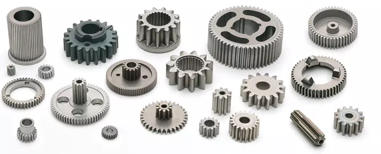
Splined shafts are the most common types of bearings for machine tools. They are made of a wide variety of materials, including metals and non-metals such as Delrin and nylon. They are often fabricated to reduce deflection. The tooth profile will become deformed with time, as the shaft is used over a long period of time. Splined shafts are available in a huge range of materials and lengths.
Functions
Splined shafts are used in a variety of applications and industries. They are an effective anti-rotational device, as well as a reliable means of transmitting torque. Other types of shafts are available, including key shafts, but splines are the most convenient for transmitting torque. The following article discusses the functions of splines and why they are a superior choice. Listed below are a few examples of applications and industries in which splines are used. Splined shafts can be of several styles, depending on the application and mechanical system in question. The differences between splined shaft styles include the design of teeth, overall strength, transfer of rotational concentricity, sliding ability, and misalignment tolerance. Listed below are a few examples of splines, as well as some of their benefits. The difference between these styles is not mutually exclusive; instead, each style has a distinct set of pros and cons. A splined shaft is a cylindrical shaft with teeth or ridges that correspond to a specific angular position. This allows a shaft to transfer torque while maintaining angular correspondence between tracks. A splined shaft is defined as a cylindrical member with several grooves cut into its circumference. These grooves are equally spaced around the shaft and form a series of projecting keys. These features give the shaft a rounded appearance and allow it to fit perfectly into a grooved cylindrical member. While the most common applications of splines are for shortening or extending shafts, they can also be used to secure mechanical assemblies. An “involute spline” spline has a groove that is wider than its counterparts. The result is that a splined shaft will resist separation during operation. They are an ideal choice for applications where deflection is an issue. A spline shaft’s radial torsion load distribution is equally distributed, unless a bevel gear is used. The radial torsion load is evenly distributed and will not exert significant load concentration. If the spline couplings are not aligned correctly, the spline connection can fail quickly, causing significant fretting fatigue and wear. A couple of papers discuss this issue in more detail.
Types
There are many different types of splined shafts. Each type features an evenly spaced helix of grooves on its outer surface. These grooves are either parallel or involute. Their shape allows them to be paired with gears and interchange rotary and linear motion. Splines are often cold-rolled or cut. The latter has increased strength compared to cut spines. These types of shafts are commonly used in applications requiring high strength, accuracy, and smoothness. Another difference between internal and external splined shafts lies in the manufacturing process. The former is made of wood, while the latter is made of steel or a metal alloy. The process of manufacturing splined shafts involves cutting furrows into the surface of the material. Both processes are expensive and require expert skill. The main advantage of splined shafts is their adaptability to a wide range of applications. In general, splined shafts are used in machinery where the rotation is transferred to an internal splined member. This member can be a gear or some other rotary device. These types of shafts are often packaged together as a hub assembly. Cleaning and lubricating are essential to the life of these components. If you’re using them on a daily basis, you’ll want to make sure to regularly inspect them. Crowned splines are usually involute. The teeth of these splines form a spiral pattern. They are used for smaller diameter shafts because they add strength. Involute splines are also used on instrument drives and valve shafts. Serration standards are found in the SAE. Both kinds of splines can also contain a ball bearing for high torque. The difference between the two types of splines is the number of teeth on the shaft. Internal splines have many advantages over external ones. For example, an internal spline shaft can be made using a grinding wheel instead of a CNC machine. It also uses a more accurate and economical process. Furthermore, it allows for a shorter manufacturing cycle, which is essential when splining high-speed machines. In addition, it stabilizes the relative phase between the spline and thread.
Manufacturing methods
There are several methods used to fabricate a splined shaft. Key and splined shafts are constructed from two separate parts that are shaped in a synchronized manner to transfer torque uniformly. Hot rolling is one method, while cold rolling utilizes low temperatures to form metal. Both methods enhance mechanical properties, surface finishes, and precision. The advantage of cold rolling is its cost-effectiveness. Cold forming is one method, as well as machining and assembling. Cold forming is a unique process that allows the spline to be shaped to the desired shape. The resulting shape provides maximum contact area and torsional strength. Standard splines are available in standard sizes, but custom lengths can also be ordered. CZPT offers various auxiliary equipment, such as mating sleeves and flanged bushings. Cold forging is another method. This method produces long splined shafts that are used in automobile propellers. After the spline portion is cut out, it is worked on in a hobbing machine. Work hardening enhances the root strength of the splined portion. It can be used for bearings, gears, and other mechanical components. Listed below are the manufacturing methods for splined shafts. Parallel splines are the simplest of the splined shaft manufacturing methods. Parallel splines are usually welded to shafts, while involute splines are made of metal or non-metals. Splines are available in a wide variety of lengths and materials. The process is usually accompanied by a process called milling. The workpiece rotates to produce the serrated surface. Splines are internal or external grooves in a splined shaft. They work in combination with keyways to transfer torque. Male and female splines are used in gears. Female and male splines correspond to one another to ensure proper angular correspondence. Involute splines have more surface area and thus are stronger than external splines. Moreover, they help the shaft fit into a grooved cylindrical member without misalignment. A variety of other methods of manufacturing a splined shaft can be used to produce a splined shaft. Spline shafts can be produced using broaching and shaping, two precision machining methods. Broaching uses a metal tool with successively larger teeth to remove metal and create ridges and holes in the surface of a material. However, this process is expensive and requires special expertise.
Applications
The splined shaft is a mechanical component with a helix-like shape formed by the equal spacing of grooves in a circular ring. The splines can either have parallel or involute sides. The splines minimize stress concentration in stationary joints and can be used in both rotary and linear motion. In some cases, splines are rolled rather than cut. The latter is more durable than cut splines and is often used in applications requiring high strength, accuracy, and smooth finish. Splined shafts are commonly made of carbon steel. This alloy steel has a low carbon content, making it easy to work with. Carbon steel is a great choice for splines because it is malleable. Generally, high-quality carbon steel provides a consistent motion. Steel alloys are also available that contain nickel, chromium, copper, and other metals. If you’re unsure of the right material for your application, you can consult a spline chart. Splines are a versatile mechanical component. They are easy to cut and fit. Splines can be internal or external, with teeth positioned at equal intervals on both sides of the shaft. This allows the shaft to engage with the hub around the entire circumference of the hub. It also increases load capacity by creating a constant multiple-tooth point of contact with the hub. For this reason, they’re used extensively in rotary and linear motion. Splined shafts are used in a wide variety of industries. CZPT Inc. offers custom and standard splined shafts for a variety of applications. When choosing a splined shaft for a specific application, consider the surrounding mated components, torque requirements, and size requirements. These three factors will make it the ideal choice for your rotary equipment. And you’ll be pleased with the end result! There are many types of splines and their applications are endless. They transfer torque and angular misalignment between parts, and they also enable the axial rotation of assembled components. Therefore, splines are an essential component of machinery and are used in a wide range of applications. This type of shaft can be found in various types of machines, from household appliances to industrial machinery. So, the next time you’re looking for a splined shaft, make sure you look for a splined one.
Product description The spline is a type of linear movement technique. When spline motions along the precision floor Shaft by balls, the torque is transferred. The spline has compact construction. It can transfer the Above load and motive CZPT . It has CZPT er life time. At present the manufacturing facility manufacture two sorts of spline, particularly convex spline and concave spline. Typically the convex spline can just take larger radial load and torque than concave spline.
Merchandise name
Ball spline
Model
GJZ,GJZA,GJF,GJH,GJZG,GJFG,
Dia
15mm-150mm
Material
Bearing Metal
Precision Class
Regular/ CZPT / Precise
Bundle
Plastic bag, box, carton
MOQ
1pc
Specs Ball variety:φ16-φ250 High velocity , substantial accuracy Hefty load , CZPT life Versatile motion,low power use High movement pace Hefty load and CZPT service daily life Applicationgs:semiconductor equipment,tire machinery,monocrystalline silicon furnace,healthcare rehabilitation gear
Company profile
HangZhou YIGONG has a total overall performance laboratory of rolling functional factors, substantial-velocity ball screw pair 60m/min managing sounds 70dB, large-velocity rolling linear information pair 60m/min operating noise 68dB, for precision horizontal machining heart batch matching ball screw pair, rolling guidebook pair, to accomplish every axis CZPT moving speed 40m/min, positioning accuracy .002mm, recurring positioning precision .001mm. Our equipments import from Japan and Germany and so on.
FAQ
Why decide on AZI CZPT ? With a lot more than 60 a long time of production expertise, top quality assurance,manufacturing facility right price.
How can I get a sample to check the top quality? We estimate according to your drawing, the price tag is ideal, sign the sample record. What is your major products ? Our Primary products are consist of ball screw,linear information,arc linear manual,ball spline and ball screw linear guide rail module.
The PTO shaft transmits power from the tractor to the PTO energy attachment. This enables the tractor to electrical power a range of tractor tools, including flail mowers, sawdust, rotary tillers, excavators, and much more. PTO shaft connectors on tractors are not standardized, which can direct to complications when connecting the PTO shaft. For case in point, on some outdated tractors, the connecting flange is reasonably near to the tractor by itself, so the link is tough and there is a potential basic safety hazard.
PTO shafts range in dimensions and you will need to find a matching coupling to drag. Attaching the instrument to the tractor must be simple. If you have to elevate the unit off the ground to hook up to the driveshaft, or if the driveshaft is too long, forcing the relationship could harm each. If you have an present PTO shaft handy, it really is effortless to affirm your size. Close it and evaluate from PTO yoke to yoke.
Despite the fact that we consider delight in getting “Collar Experts”, our expertise in sourcing quality merchandise has produced Lucas Industrial a valued provider of other energy transmission products as well. 1st amongst these are linear bearings with interchanges obtainable for virtually all types and dimensions. Other electricity transmission items obtainable by way of Lucas Industrial consist of leaf chain, roller chain, lumber conveying chain, rigid couplings, ball bearings, and sprockets.assures the steadiness and consistency of the essential function of components.
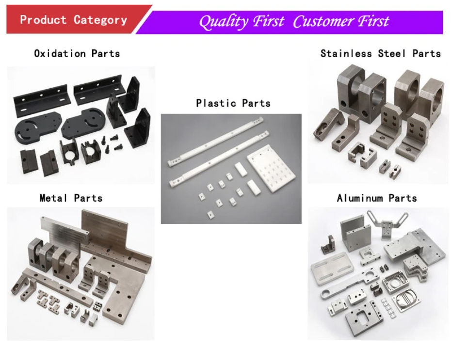
Overview
Fast Details
Applicable Industries:
Creating Substance Stores, Manufacturing Plant, Farms, Building works , Energy & Mining, Food & Beverage Stores
Construction:
Deep Groove, Deep Groove
Variety:
Ball, Ball
Application:
skateboard/roller skate/inline skate
Material:
Chrome Metal GCR15
Clearance:
C0,C2,C3
The organization was certified by ISO9001:2008 Good quality Administration Technique.
Certification:
ISO9001
name:
608zz skateboard bearings
Noise Degree:
Z1,Z2,Z3,Z4
Technological innovation:
–Pushed (outer) yoke exact same as push yoke but is mounted on the apply. There are two types of shafts, domestic and metric, which are identifiable by their designs. Domestic are typically 1 of 4 shapes: spherical, square, rectangle or splined. Metric are: bell, star or football formed. In either case the main (entrance) shaft is the same form as the secondary shaft, only larger so that the secondary shaft fits within. This makes it possible for a telescoping result to take spot when the employ is elevated on the 3 pt. or during a turning movement this sort of as a bailer. All shafts have to be sized ahead of use. Connect the apply to the 3 pt. and increase and assist it. Attach the correct finish to the tractor and attempt to connect the other to the put into action. If the shaft is as well lengthy trim one of the shafts with a hack noticed and try it once more until finally it matches. This allows for the put into action to be elevated with no binding. The shafts should overlap as significantly as permitted.
Lower noise, low libration ,Higher Precision and Longevity
A novel layout that employs a simple coil spring mounted in the breather’s air passageway solves the issue. The interior of the spring does not offer a constant floor where bubbles can type, and this removes the percolating effect and resulting oil transfer.
Support:
OEM Custom-made Services
Supply Ability
Offer Capability:
2000000 Piece/Pieces for each Month 608zz abec 5
Packaging & Shipping and delivery
Packaging Information
two. Individual Paper Box/Carton/Pallet
three. As the clients’ requirement”>1. Industrial Exporting Package with anti-tarnish paper/Carton/Pallet
two. Personal Paper Box/Carton/Pallet
3. As the clients’ necessity
Port
Qingdao/Shanghai/Tianjin/Guangzhou
On the internet Customization
HangZhou At any time-Electricity transmission Co. Ltd. 1 of department of At any time-Electricity Group – the greatest China transmisssion provider. With 1200 worker and precision products, we create substantial good quality merchandise to United states of america and EU and other regions.
2809 Skateboard Bearing 2809 Deep Groove Ball Bearing for Hand Fidget Spinner Toy
Product parameter
Custom made all kinds of bearing
Bearing NO.
608
Bore Dia (d)
8mm
Outer Dia (D)
22mm
Width (B)
7mm
Seal Type
Shielded or Seal and Open are accessible.
Content
52100 Chrome metal, stainless steel and ceramic are offered.
Dynamic Load Ranking (Cr) (KN)
3.35
Static Load Rating (Cor) (KN)
one.4
Max Velocity (Grease) (X1000 RPM)
26
Max Speed (Oil) (X1000 RPM)
34
Ball Qty
7
Fat (g) (kg)
.012
Precision Charge
ABEC Grades 1, 3, 5, 7, and 9 are offered. Also, the equivalent ISO lessons.
N0.
Bore
O.D
Width
Chamfer
Load Rating
Maximuum Seed
Weight
mm
mm
mm
mm
Dynamic
Static
Grease
Oil
Kg/pcs
Cr
Cor
r/min
r/min
605
5
14
5
.2
1.33
.505
32000
40000
.0035
606
six
seventeen
six
.3
two.19
.865
30000
38000
.006
607
seven
19
six
.three
2.24
.91
28000
36000
.008
608
eight
22
seven
.three
3.35
one.4
26000
34000
.012
609
nine
24
7
.3
three.4
one.forty five
24000
32000
.014
6000
10
26
eight
.3
four.fifty five
one.ninety six
22000
30000
.019
6001
twelve
28
eight
.three
five.one
2.39
19000
26000
.021
6002
15
32
nine
.three
5.six
two.83
18000
24000
.03
6003
seventeen
35
10
.3
6.8
three.35
17000
22000
.039
6004
twenty
forty two
twelve
.six
9.four
five.05
15000
19000
.069
6005
twenty five
forty seven
twelve
.6
ten.1
5.85
14000
18000
.08
6006
thirty
fifty five
13
.6
thirteen.2
eight.3
12000
15000
.116
6007
35
62
14
1
16
10.3
ten thousand
14000
.one hundred fifteen
6008
forty
sixty eight
15
one
sixteen.eight
11.5
8000
11000
.19
Remember to consult us for any bearings unlisted listed here.
Solution display
Far more Item
Firm Information
Started in Could 1979, the year when China started its open up plan, we are a stated owned complete organization combining “sector & buying and selling, technologies & trading”. In 2002, our firm modified from state-owned business to personal owned company.
Backed up by powerful financial power, sophisticated services & technologies, and enormous production functionality of several factories, Xinguang has been developing rapidly in organization since its basis establish long- phrase and friendly relationship with numerous customers from most places of the globe.
Now, our staff are much more than sixty, in which 50 percent of them are engineers. Probably what can make us different from other buying and selling organizations is that we have a unique workers of both businessmen and skilled mechanical engineers, who have been operating in the sector for years. This function of us acts an essential function in good quality management, value handle, and provider functionality.
Bearings & electricity transmission components are our principal export goods. Our bearings, chains, sprockets, pulleys, tapered bushings, and shaft collars have been mass -exported to a variety of countries and locations this sort of as North America, Europe, Africa, South The united states and Southeast Asia.
Our top quality products, prompt shipping, and aggressive pricing have received us much praise from the customers. By the challenging function of our employees by way of thirty several years, Xinguang has grow to be one of the main exporters of bearings& energy transmission factors in China.
We welcome consumers from the entire entire world to cooperate with us.
A single aspect of our software consulting is that we have been amassing and combining the knowledge in chain and sprocket applications in numerous areas for many years. This is especially interesting for us each time clients strategy us with some exceeding and tough demands.In this way, our goods have ongoing to achieve market acceptance and consumers satisfaction in excess of the previous few many years.
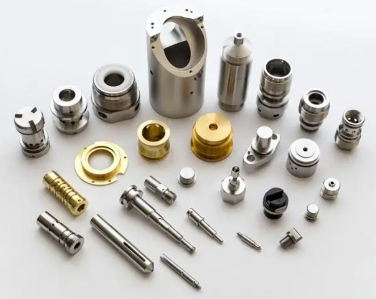
Overview
Swift Information
Relevant Industries:
Producing Plant
Manufacturer Identify:
OEM
OEM Service:
Help
Tolerance:
.01-.05mm or Personalized
Certification:
ISO9001, SGS
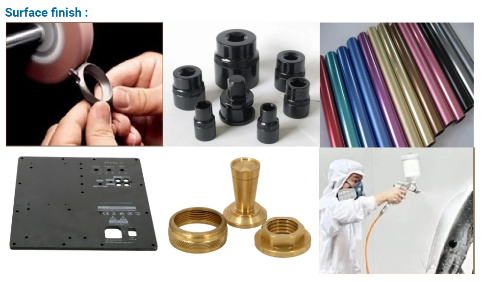
Surface Remedy:
Sandblasting,Polishing,Anodize, Zinc,Nickel,Chrome,Plating, and so on.
Software:
Vehicle,Health-related EquipmentThis novel breather plug attributes a spring that helps prevent oil bubbles from forming and percolating to the exterior.s,Electric Appliance,Hardware,etc.
Dimension:
As Customers’ Request
Gear:
Milling/Lathe/Drilling/Four/A few Axis CNC Machining Middle
To offer generation layout, creation and technical service, mould development and processing, etc
Drawing Format:
PRO/E, Auto CAD, Solid Works,IGS,UG, CAD/CAM/CAE
Testing Equipment
Digital Peak Gauge, caliper, Coordinate measuring equipment, projection equipment, roughness tester, hardness tester and so oClose up of two yokes with the universal joint. Notice the slight oozing of grease from the UJ seal finishes, the clump of grease is from inside of the yoke splined shaft region –Drive (outer) yoke has a woman (common spline) gap and “Y” form end that is the common joint (UJ) mount. –UJ is a cross formed casting getting roller bearings enclosed with caps at all 4 details and is held into the yoke with 4 “C” clips –Inner yoke and generate shaft is one more yoke welded to the push finish, of the travel shaft. –Pushed shaft and internal yoke is the pushed shaft that rides inside of the push shaft and has a yoke welded at the driven conclude –UJ yet another UJ as aboven
Industry employed
Machinery heavy obligation tools electronic unit Car spare elements optical telecommunication
Packing
Eco-welcoming pp bag / EPE Foam /Carton packing containers or wooden boxes As customer’s distinct demands