Product Description
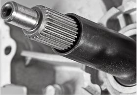
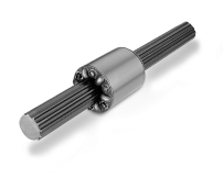
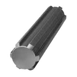
Key attributes of Customized CNC Machining High Precise transmission Steel Large Spline Gear Shaft
Industry-specific attributes of Customized CNC Machining High Precise transmission Steel Large Spline Gear Shaft
| CNC Machining or Not | Cnc Machining |
| Material Capabilities | Aluminum, Brass, Bronze, Copper, Hardened Metals, Precious Metals, Stainless steel, Steel Alloys |
Other attributes of Customized CNC Machining High Precise transmission Steel Large Spline Gear Shaft
| Place of Origin | ZheJiang , China |
| Type | Broaching, DRILLING, Etching / Chemical Machining, Laser Machining, Milling, Other Machining Services, Turning, Wire EDM |
| Model Number | OEM |
| Brand Name | OEM |
| Material | Metal |
| Process | Cnc Machining+deburrs |
| Surface treatment | Customer’s Request |
| Equipment | CNC Machining Centres / Core moving machine / precision lathe / Automatic loading and unloading equipment |
| Processing Type | Milling / Turning / Stamping |
| OEM/ODM | OEM & ODM CNC Milling Turning Machining Service |
| Drawing Format | 2D/(PDF/CAD)3D(IGES/STEP) |
| Our Service | OEM ODM Customers’drawing |
| Materials Avaliable | Stainless Steel / Aluminum / Metals / Copper / Plastic |
Best Seller of 304 Stainless Steel Polishing Finishing CNC Machining Bracket for Laser Cutting
About YiSheng
| Business Type | Factory / Manufacturer |
| Service | CNC Machining |
| Turning and Milling | |
| CNC Turning | |
| OEM Parts | |
| Material | 1). Aluminum: AL 6061-T6, 6063, 7075-T etc |
| 2). Stainless steel: 303,304,316L, 17-4(SUS630) etc | |
| 3). Steel: 4140, Q235, Q345B,20#,45# etc. | |
| 4). Titanium: TA1,TA2/GR2, TA4/GR5, TC4, TC18 etc | |
| 5). Brass: C36000 (HPb62), C37700 (HPb59), C26800 (H68), C22000(H90) etc | |
| 6). Copper, bronze, Magnesium alloy, Delrin, POM,Acrylic, PC, etc. | |
| Finish | Sandblasting, Anodize color, Blackenning, Zinc/Nickl Plating, Polish, |
| Power coating, Passivation PVD, Titanium Plating, Electrogalvanizing, | |
| electroplating chromium, electrophoresis, QPQ(Quench-Polish-Quench), | |
| Electro Polishing,Chrome Plating, Knurl, Laser etch Logo, etc. | |
| Main Equipment | CNC Machining center, CNC Lathe, precision lathe |
| Automatic loading and unloading equipment | |
| Core moving machine | |
| Drawing format | STEP,STP,GIS,CAD,PDF,DWG,DXF etc or samples. |
| Tolerance | +/-0.001mm ~ +/-0.05mm |
| Surface roughness | Ra 0.1~3.2 |
| Test Equipment | Complete test lab with Projector, High-low temperature test chamber, Tensile tester Gauge, Salt fog test |
| Inspection | Complete inspection lab with Micrometer, Optical Comparator, Caliper Vernier,CMM |
| Depth Caliper Vernier, Universal Protractor, Clock Gauge | |
| Capacity | CNC turning work range: φ0.5mm-φ150mm*300mm |
| CNC center work range: 510mm*850mm*500mm | |
| Core moving machine work range: φ32mm*85mm | |
| Gerenal Tolerance: (+/-mm) |
CNC Machining: 0.005 |
| Core moving: 0.005 | |
| Turning: 0.005 | |
| Grinding(Flatness/in2): 0.003 | |
| ID/OD Grinding: 0.002 | |
| Wire-Cutting: 0.002 |
RFQ of Customized CNC Machining High Precise transmission Steel Large Spline Gear Shaft /* January 22, 2571 19:08:37 */!function(){function s(e,r){var a,o={};try{e&&e.split(“,”).forEach(function(e,t){e&&(a=e.match(/(.*?):(.*)$/))&&1
| Certification: | ISO9001 |
|---|---|
| Standard: | DIN, ASTM, GOST, GB, JIS, ANSI, BS |
| Customized: | Customized |
| Customization: |
Available
| Customized Request |
|---|
.shipping-cost-tm .tm-status-off{background: none;padding:0;color: #1470cc}
|
Shipping Cost:
Estimated freight per unit. |
about shipping cost and estimated delivery time. |
|---|
| Payment Method: |
|
|---|---|
|
Initial Payment Full Payment |
| Currency: | US$ |
|---|
| Return&refunds: | You can apply for a refund up to 30 days after receipt of the products. |
|---|

How do spline shafts contribute to efficient power transmission?
Spline shafts play a vital role in enabling efficient power transmission in various mechanical systems. Here’s a detailed explanation of how spline shafts contribute to efficient power transmission:
1. Torque Transmission:
Spline shafts are designed to transmit torque from one component to another. They provide a positive, non-slip connection that allows for efficient power transfer without slippage or loss of energy. The splines on the shaft engage with corresponding splines on the mating component, creating a strong mechanical connection for torque transmission.
2. Load Distribution:
Spline shafts distribute the applied load evenly across the engagement surfaces. The teeth or grooves on the shaft’s spline profile ensure that the load is shared across multiple contact points. This even load distribution helps prevent localized stress concentrations and reduces the risk of premature wear or failure. Efficient load distribution ensures that power is transmitted smoothly and reliably.
3. Misalignment Compensation:
Spline shafts can accommodate a certain degree of misalignment between the mating components. The spline profile design allows for angular or parallel misalignment without compromising the power transmission capability. This misalignment compensation capability is crucial in maintaining efficient power transmission in situations where perfect alignment is challenging or subject to variations.
4. High Torque Capacity:
Spline shafts are designed to withstand high torque levels. The spline profile, engagement length, and material selection are optimized to handle the expected torque requirements. This high torque capacity ensures that the shaft can efficiently transmit power without experiencing excessive deflection or failure under normal operating conditions.
5. Torsional Stiffness:
Spline shafts exhibit high torsional stiffness, which means they resist twisting or torsional deflection when subjected to torque. The shaft’s design, including its diameter, spline profile, and material properties, contributes to its torsional stiffness. High torsional stiffness minimizes power loss due to deformation or flexing of the shaft, allowing for efficient power transmission.
6. Reliable Connection:
Spline shafts provide a reliable and repeatable connection between the driving and driven components. Once properly engaged, the spline shaft maintains its connection, ensuring consistent power transmission over time. This reliability is crucial in maintaining efficiency and preventing power loss or interruptions during operation.
7. Minimal Backlash:
Backlash refers to the slight rotational play or clearance between mating components. Spline shafts, when properly designed and manufactured, can minimize backlash in the power transmission system. Reduced backlash ensures smoother operation, improved accuracy, and efficiency by minimizing power losses associated with reversing or changing direction.
8. Compact Design:
Spline shafts offer a compact and space-efficient solution for power transmission. Their design allows for a relatively small footprint while providing robust torque transmission capabilities. The compact design is particularly advantageous in applications where space is limited, such as automotive drivetrains or compact machinery.
By incorporating spline shafts into mechanical systems, engineers can achieve efficient power transmission, ensuring that power is effectively transferred from the driving source to the driven components. The unique design features of spline shafts enable reliable torque transmission, even load distribution, misalignment compensation, high torque capacity, torsional stiffness, reliable connections, minimal backlash, and compactness.

How do spline shafts handle variations in load capacity and weight?
Spline shafts are designed to handle variations in load capacity and weight in mechanical systems. Here’s how they accomplish this:
1. Material Selection:
Spline shafts are typically made from high-strength materials such as steel or alloy, chosen for their ability to withstand heavy loads and provide durability. The selection of materials takes into account factors such as tensile strength, yield strength, and fatigue resistance to ensure the shaft can handle variations in load capacity and weight.
2. Engineering Design:
Spline shafts are designed with consideration for the anticipated loads and weights they will encounter. The dimensions, profile, and number of splines are determined based on the expected torque requirements and the magnitude of the applied loads. By carefully engineering the design, spline shafts can handle variations in load capacity and weight while maintaining structural integrity and reliable performance.
3. Load Distribution:
The interlocking engagement of spline shafts allows for effective load distribution along the length of the shaft. This helps distribute the applied loads evenly, preventing localized stress concentrations and minimizing the risk of deformation or failure. By distributing the load, spline shafts can handle variations in load capacity and weight without compromising their performance.
4. Structural Reinforcement:
In applications with higher load capacities or heavier weights, spline shafts may incorporate additional structural features to enhance their strength. This can include thicker spline teeth, larger spline diameters, or reinforced sections along the shaft. By reinforcing critical areas, spline shafts can handle increased loads and weights while maintaining their integrity.
5. Lubrication and Surface Treatment:
Proper lubrication is essential for spline shafts to handle variations in load capacity and weight. Lubricants reduce friction between the mating surfaces, minimizing wear and preventing premature failure. Additionally, surface treatments such as coatings or heat treatments can enhance the hardness and wear resistance of the spline shaft, improving its ability to handle varying loads and weights.
6. Testing and Validation:
Spline shafts undergo rigorous testing and validation to ensure they meet the specified load capacity and weight requirements. This may involve laboratory testing, simulation analysis, or field testing under real-world conditions. By subjecting spline shafts to thorough testing, manufacturers can verify their performance and ensure they can handle variations in load capacity and weight.
Overall, spline shafts are designed and engineered to handle variations in load capacity and weight by utilizing appropriate materials, optimizing the design, distributing loads effectively, incorporating structural reinforcement when necessary, implementing proper lubrication and surface treatments, and conducting thorough testing and validation. These measures enable spline shafts to reliably transmit torque and handle varying loads in diverse mechanical applications.

What are the key components and design features of a spline shaft?
A spline shaft consists of several key components and incorporates specific design features to ensure its functionality and performance. Here’s a detailed explanation:
1. Shaft Body:
The main component of a spline shaft is the shaft body, which provides the structural integrity and serves as the base for the spline features. The shaft body is typically cylindrical in shape and made from materials such as steel, stainless steel, or other alloyed metals. The material selection depends on factors like the application requirements, torque loads, and environmental conditions.
2. Splines:
The splines are the key design feature of a spline shaft. They are ridges or teeth that are machined onto the surface of the shaft. The splines create the interlocking mechanism with mating components, allowing for torque transmission and relative movement. The number, size, and shape of the splines can vary depending on the application requirements and design specifications.
3. Spline Profile:
The spline profile refers to the specific shape or geometry of the splines. Common types of spline profiles include involute, straight-sided, and serrated. The spline profile is chosen based on factors such as the torque transmission requirements, load distribution, and the desired engagement characteristics with mating components. The spline profile ensures optimal contact and torque transfer between the spline shaft and the mating component.
4. Spline Fit:
The spline fit refers to the dimensional relationship between the spline shaft and the mating component. It determines the clearance or interference between the splines, ensuring proper engagement and transmission of torque. The spline fit can be categorized into different classes, such as clearance fit, transition fit, or interference fit, based on the desired level of clearance or interference.
5. Surface Finish:
The surface finish of the spline shaft is crucial for its performance. The splines and the shaft body should have a smooth and consistent surface finish to minimize friction, wear, and the risk of stress concentrations. The surface finish can be achieved through machining, grinding, or other surface treatment methods to meet the required specifications.
6. Lubrication:
To ensure smooth operation and reduce wear, lubrication is often employed for spline shafts. Lubricants with appropriate viscosity and lubricating properties are applied to the spline interface to minimize friction, dissipate heat, and prevent premature wear or damage to the splines and mating components. Lubrication also helps in maintaining the functionality and prolonging the service life of the spline shaft.
7. Machining Tolerances:
Precision machining is critical for spline shafts to achieve the required dimensional accuracy and ensure proper engagement with mating components. Tight machining tolerances are maintained during the manufacturing process to ensure the spline profile, dimensions, and surface finish meet the specified design requirements. This ensures the interchangeability and compatibility of spline shafts in various applications.
In summary, the key components and design features of a spline shaft include the shaft body, splines, spline profile, spline fit, surface finish, lubrication, and machining tolerances. These elements work together to enable torque transmission, relative movement, and load distribution while ensuring the functionality, durability, and performance of the spline shaft.


editor by CX 2024-04-17