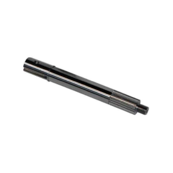
C45 inductiegeharde spie-as
C45-uitwendige spline-as met inductieharding tot HRC55-60 voor op maat gemaakte, tekening-gedefinieerde krachtoverbrengingsinterfaces.
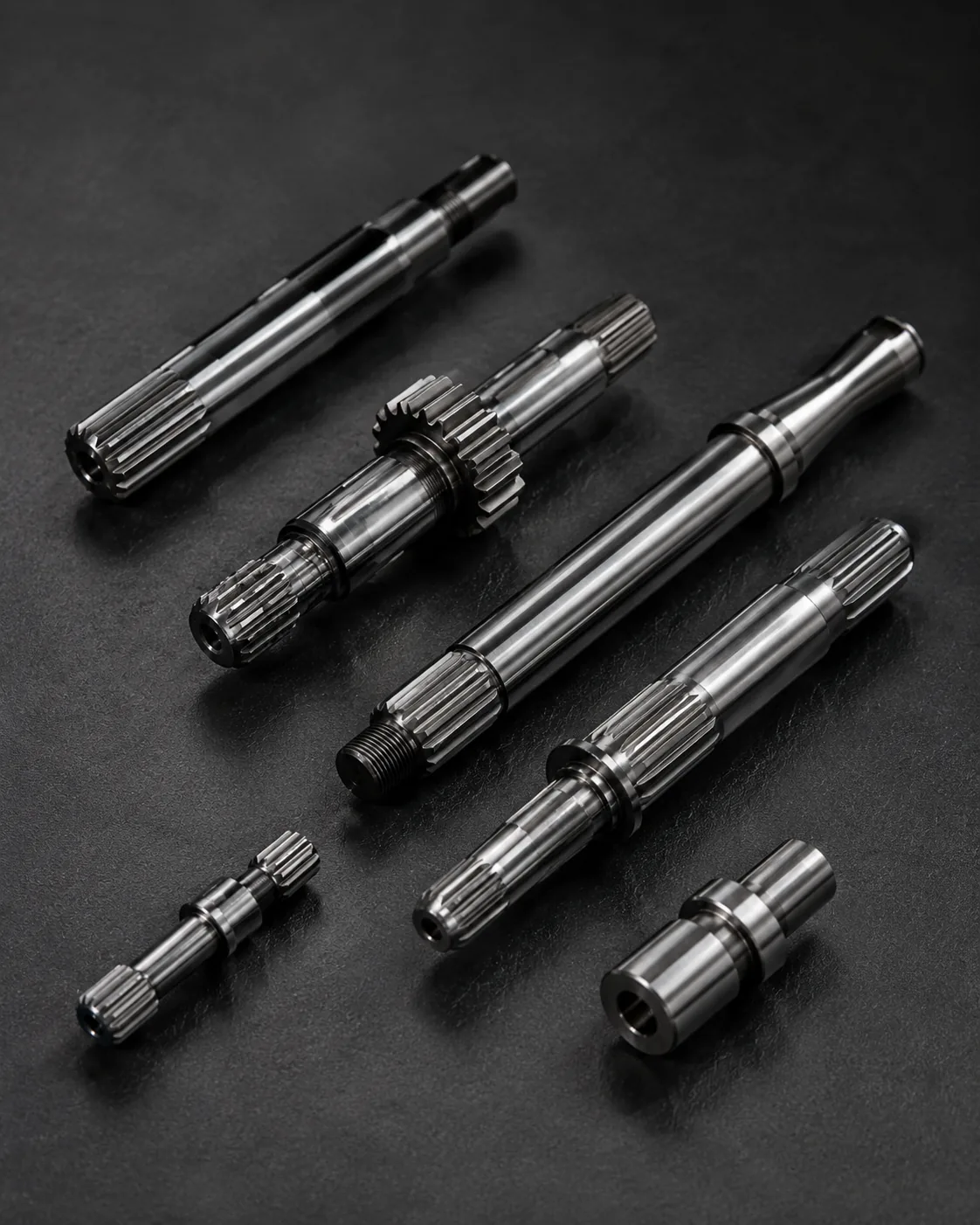
C45 inductiegeharde spie-as — This C45 external spline shaft combines a machined spline interface with an induction-hardened surface condition. This item uses C45 material with induction hardening to HRC55-60. Final tooth geometry, shaft dimensions and fit are manufactured to the customer drawing so the spline can be matched to the actual hub, gear, sleeve or driveline connection.
Product overview
This C45 external spline shaft combines a machined spline interface with an induction-hardened surface condition. This item uses C45 material with induction hardening to HRC55-60. Final tooth geometry, shaft dimensions and fit are manufactured to the customer drawing so the spline can be matched to the actual hub, gear, sleeve or driveline connection.
For quotation, define the spline as part of the complete mating interface. Tooth geometry, adjacent journals, shoulders, grooves, threads and bearing seats should be dimensioned from functional datums so the finished shaft can be inspected in the same relationship in which it operates. Dimensions not listed on this page are manufactured according to the customer-approved drawing.
Technical specifications
The values below describe this product configuration. Any dimension, tolerance, rating or fit not shown should be stated on the enquiry drawing before production.
| Material | C45 |
|---|---|
| Heat treatment | Induction hardening |
| Hardness | HRC55-60 |
| Precision designation | DIN3963-7 grade |
Spline geometry and mating interface
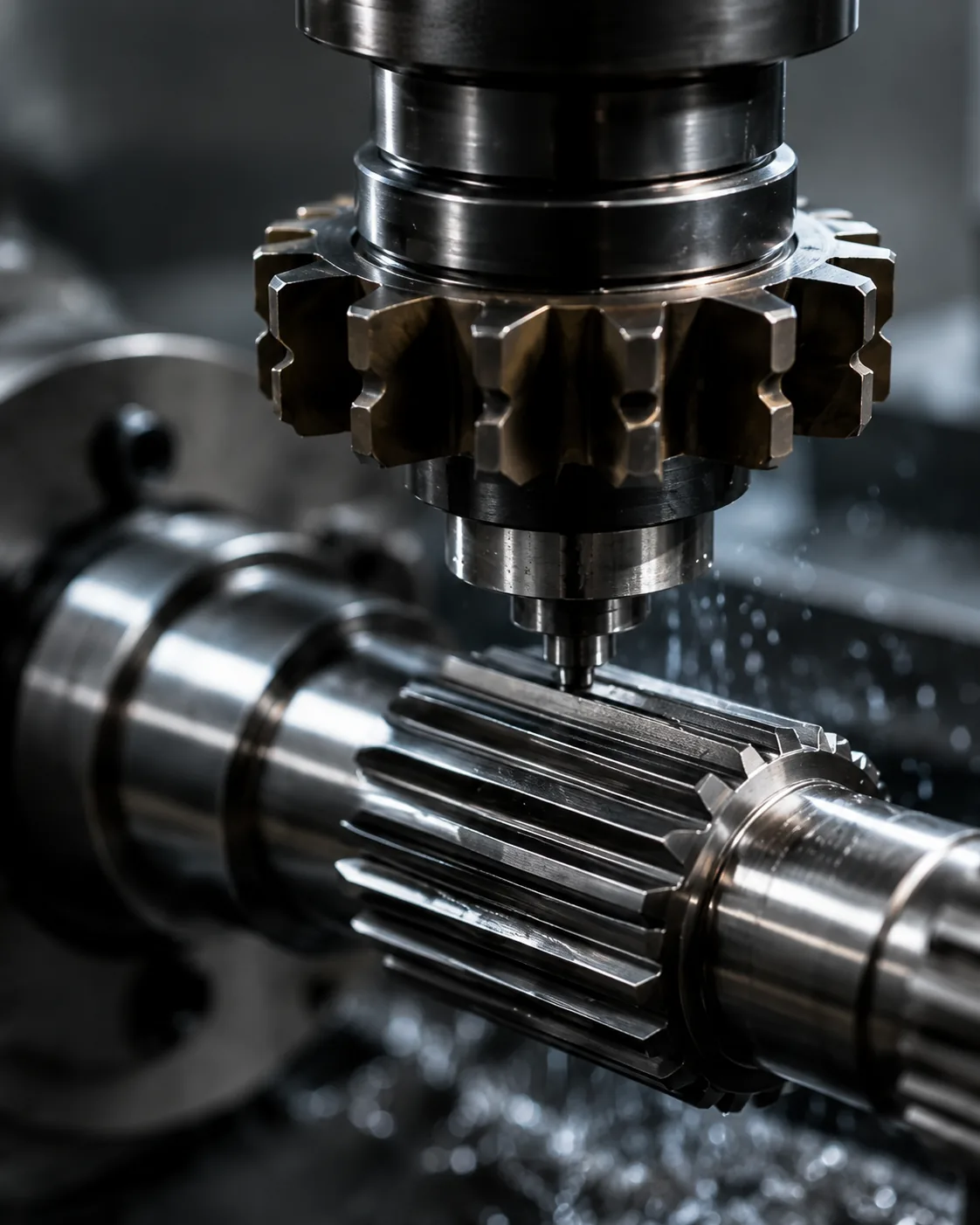
The spline cannot be selected from nominal shaft diameter alone. Confirm module or pitch system, tooth count, pressure angle, major and minor diameters, effective engagement, tooth thickness or space-width basis, end relief and the required fit with the mating member. If the connection is intended to slide axially, also state the travel, lubrication method and permissible clearance. If it is fixed, define axial location and the features that carry or react thrust.
Datum relationships matter whenever the spline works with a bearing seat, gear, seal land or locating shoulder. A tooth form may be individually within tolerance yet still produce uneven contact if the spline axis is not controlled relative to the functional journals. Put runout, position or concentricity requirements on the drawing only where they protect assembly performance, and identify the datum used for both machining and inspection.
Material, heat treatment and surface condition
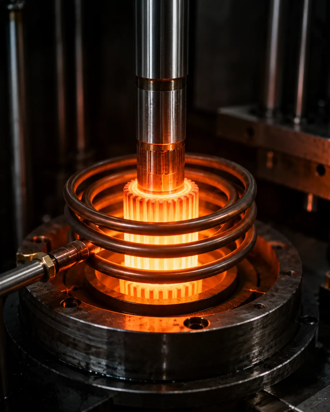
C45 is specified for this configuration together with induction hardening to HRC55-60. Induction hardening is a localized thermal process, so the drawing should identify the functional hardened zone and any surfaces that must retain a different condition. If hardness depth, transition zone or core properties are critical, add those requirements to the drawing instead of relying on surface hardness alone.
Material condition, heat treatment and finish should be reviewed as one process chain. Rough machining before heat treatment can leave stock for later finishing; thermal processing can change size or straightness; final grinding or hard finishing may be required only on features whose tolerance or surface condition demands it. State the finished requirement rather than prescribing an unnecessary process unless the process itself is part of the approved design.
Application and duty review
The mating assembly and operating duty determine where this configuration is appropriate. Typical RFQ information includes the mating internal spline, transmitted torque, rotational speed, shock or reversing load, lubrication, operating environment and whether the connection is fixed or permits axial movement.
For a new design, share the expected continuous and peak torque, speed range, duty cycle, shock or reversing load, radial or axial loads that interact with the shaft, lubrication and environmental exposure. For a replacement component, include the mating part and photographs of wear patterns. Fretting, asymmetric flank polish, pitting or looseness can indicate alignment, fit or lubrication issues that should be corrected before a replacement geometry is finalized.
Inspection and quality planning
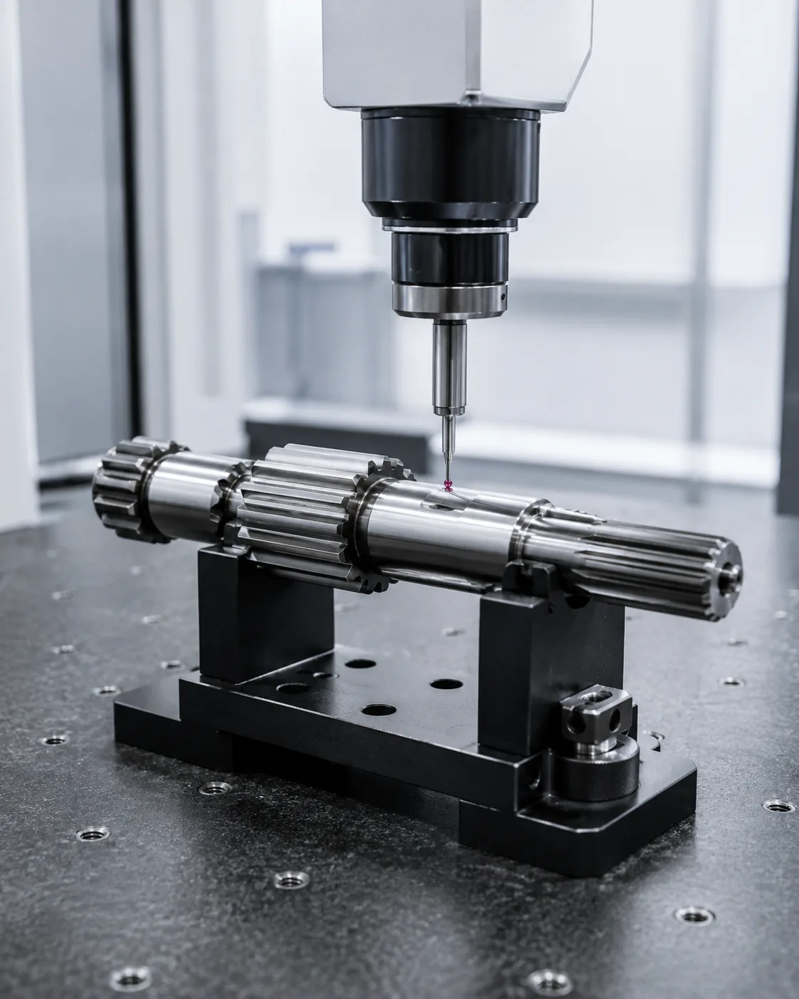
Inspection should be tied to the characteristics that control assembly and torque transfer. Depending on the drawing, this may include functional spline gaging, analytical tooth measurement, CMM checks, measurement over pins or balls where applicable, runout inspection, surface-roughness measurement and hardness testing. The measurement method should match the tolerance definition so supplier and customer evaluate the same feature in the same way.
For heat-treated shafts, identify the hardness location and whether the requirement concerns surface hardness only or also case depth and core condition. For integrated gear-and-spline parts, plan inspection of the relationship between tooth systems and journals rather than checking each feature in isolation. First-article reports should focus on the critical drawing characteristics that demonstrate fit and functional alignment.
Customization and drawing checklist
Ever-Power can evaluate custom geometry from a controlled drawing or a dimensioned interface definition. To prepare a quotation, please include the items below that apply to your assembly:
- 2D drawing with revision level, datums and the complete spline definition
- Mating hub, sleeve, gear or yoke geometry and the required fixed or sliding fit
- Material grade, heat-treatment condition, hardness and functional surface-finish requirements
- Torque, speed, shock or reversing load, duty cycle, lubrication and operating environment
- Critical runout, concentricity, axial location and bearing or seal interface requirements
- Order quantity, prototype or first-article requirement and requested inspection documentation
For this configuration, please also confirm: Spline module or pitch; tooth count; pressure angle; major and minor diameters; spline length; total length; fit class; drawing basis; standard basis for the listed precision designation.
Compare related options in the Externe spiebanenassen range or use the spline shaft drawing checklist before submitting the RFQ.
Installation, maintenance and failure-risk checks
Before assembly, confirm that both mating members are clean, undamaged and dimensionally compatible. Do not force a spline connection that binds during engagement; investigate burrs, alignment, fit and lead before applying assembly force. Where lubrication is required, use the lubricant and service interval specified for the machine or drivetrain rather than selecting a lubricant from the shaft material alone.
During service, inspect for fretting debris, pitting, abnormal flank polish, corrosion, looseness and changes in backlash. These symptoms can originate in the shaft, the mating member, support bearings or assembly alignment. Replacing only the visibly worn part without checking the mating connection can allow the same failure mechanism to continue.
Design review notes for repeatable production
Repeatability depends on more than a nominal spline callout. Keep the drawing revision, mating component, datum scheme and agreed inspection method under configuration control. If the mating hub, bearing arrangement, heat treatment or operating duty changes, review the interface again because a shaft that fits physically may not preserve the same contact pattern, clearance or load distribution.
When several features are produced on one shaft, tolerance allocation should follow function. Bearing seats normally control rotation, shoulders control axial location, and spline or gear features transfer torque. The drawing should make those relationships visible so the manufacturing plan can use stable datums and the inspection plan can reproduce the assembly logic. This is especially important after heat treatment, when straightness or feature relationship may change and final finishing may be needed on selected surfaces.
For procurement, avoid specifying process details that do not protect a functional requirement. A supplier may choose different tooling or machine sequences while still meeting the same finished geometry. Focus the RFQ on measurable acceptance criteria: material, heat treatment, hardness, tooth geometry, fit, runout, surface finish, dimensions and required reports. This keeps quotations comparable while allowing an efficient process route.
Production drawing requirements
For production, define the complete mating interface rather than only the nominal spline size. The drawing should show the tooth system, effective engagement, total length, adjacent journals and shoulders, datum references, required runout, material condition and any functional surface finish. If the part must replace an existing shaft, identify which dimensions were measured from unworn features and provide the mating hub, sleeve, yoke or gear information when available.
Also state the operating information that affects the engineering review: transmitted torque, rotational speed, reversing or shock load, lubrication, contamination, temperature, axial movement and expected assembly method. These inputs help align the manufacturing and inspection plan with the actual connection. Critical inspection characteristics should be identified on the drawing so the same acceptance basis can be used for first articles and repeat orders.
Veelgestelde vragen
These questions cover the information most often needed to turn a spline-shaft enquiry into a manufacturable and inspectable drawing.
What information is required before this spline shaft can be quoted?
Send the controlled drawing, quantity, mating spline information, material and heat-treatment requirement, torque and speed, operating environment and the inspection records you need. If the drawing is incomplete, identify the open dimensions so they can be resolved during technical review before production.
Can the spline geometry be customized?
Yes, custom module or pitch, tooth count, pressure angle, diameters, engagement and adjacent shaft features can be evaluated from the mating interface and duty. Any change to tooth geometry must be checked against the mating member because it changes fit, contact and interchangeability.
How should hardness be specified?
State the hardness value together with the measurement location and, when relevant, case-depth or core requirements. A single hardness number does not automatically define the condition of the entire shaft, especially when localized or case-hardening processes are used.
How should runout be controlled?
Tie runout to a functional datum such as a bearing journal, pilot diameter or gear reference. The tolerance should protect assembly and contact rather than simply be made as tight as possible. Show the datum and measurement condition on the drawing.
What should be checked when replacing a worn shaft?
Inspect the mating hub or sleeve as well as the shaft. Measure unworn regions where possible and document fretting, pitting, asymmetric contact or looseness. Those observations help distinguish normal wear from fit, alignment or lubrication problems.
Request a quotation
- Controlled drawing and revision
- Mating spline/interface information
- Material and heat-treatment requirement
- Operating duty and environment
- Quantity and inspection documentation
Send the drawing and application details through the enquiry form below. The technical review will focus on the mating interface, material condition, functional datums, operating duty and inspection requirements so the quotation is based on the actual component definition.
Vraag een technische offerte aan
Send the drawing, mating spline, material condition, quantity, torque/speed information and inspection requirements.