Description du produit
Description du produit
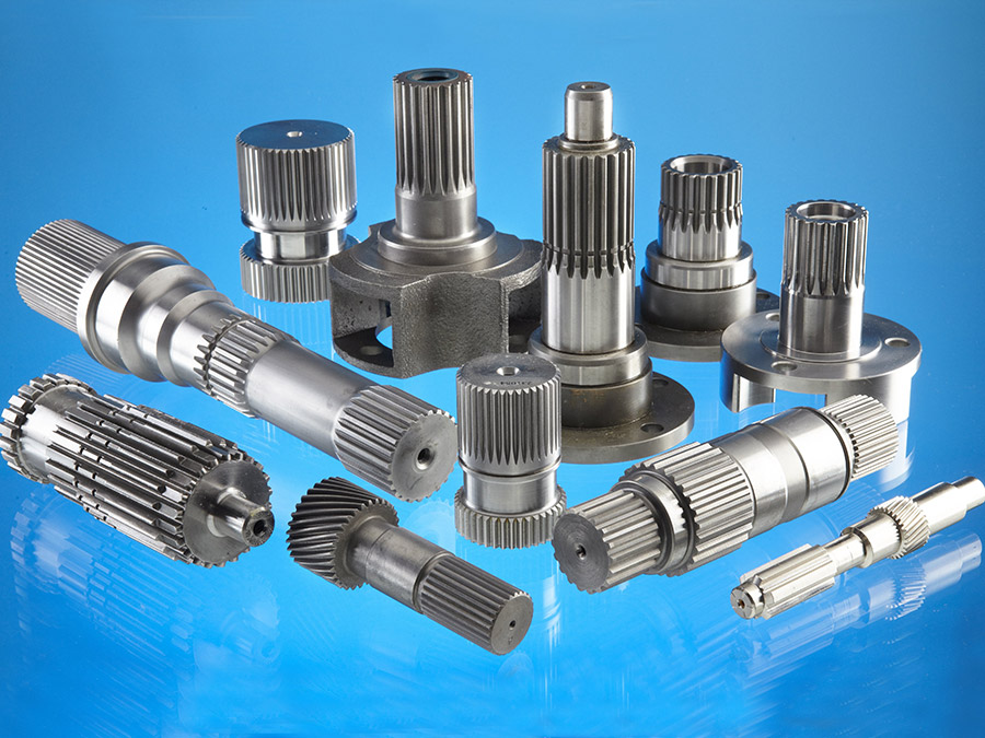
PACKUP TRUCKS.Drive Shaft
Drive shaft product model : ND05003
| Nom du produit | rear axle drive shaft |
| OEM number | FORD: BG1T4234A |
| Matériel | 40cr carbon steel |
| Hole | 5 |
| Longueur | 684(mm) |
| Spline shaft | z=30 |
| Qualité | High performance |
| Function of drive shaft | Power transmission |
| Vehicle model of drive shaft | FORD RANGER 1998/2005 |
| Processing of shaft | Forgeage |
| Surface treatment of shaft | Usually black customizable Silver, Blue, Rose Gold |
| Availability | Can be customized according to drawings |
We also sell chassis accessories for automobiles, trucks, agricultural machinery and construction machinery, including:
CVJ,Drive shaft, steering drive shaft, differential parts and assemblies, ball joints, universal joints, tire screws, and so on
Profil de l'entreprise
FAQ
Q: Which payment terms will you accept?
A: We can accept TT, Western union, paypal and cash etc
Q: When my order will be shipped?
A:Once we get payment, we will ship your order within 20 working days.
Q: Which shipping will you offer?
A:By sea, air, DHL, Fedex, TNT, UPS, EMS, SF
Q: How long does it take to my address?
A:The normal delivery time is 20days, depending on which country you are in.
Q: How can I trace my order?
A:We will send you the tracking number by email.
Q: If I am not satisfied with the products, what should I do?
A:You can contact us and tell us about your problem. We will offer exchange or repair service under warranty.
| Matériel: | 40cr Carbon Steel |
|---|---|
| Charger: | Arbre de transmission |
| Rigidité et flexibilité : | Rigidité / Essieu rigide |
| Exemples : |
US$ 50/Piece
1 pièce (commande minimale) | Commander un échantillon |
|---|
| Personnalisation : |
Disponible
| Demande personnalisée |
|---|
.shipping-cost-tm .tm-status-off{background: none;padding:0;color: #1470cc}
| Frais d'expédition :
Frais de transport estimés par unité. |
concernant les frais de livraison et le délai de livraison estimé. |
|---|
| Mode de paiement: |
|
|---|---|
|
Paiement initial Paiement intégral |
| Devise: | US$ |
|---|
| Retours et remboursements : | Vous pouvez demander un remboursement jusqu'à 30 jours après la réception des produits. |
|---|
Can spline shafts be used in both mobile and stationary machinery?
Yes, spline shafts can be used in both mobile and stationary machinery. Here’s a detailed explanation:
1. Mobile Machinery:
Spline shafts find extensive use in various types of mobile machinery. For example:
- In Automotive Applications: Spline shafts are commonly used in automotive drivetrains, where they transmit torque from the engine to the wheels. They are found in components such as the transmission, differential, and axle shafts.
- In Construction and Earthmoving Equipment: Spline shafts are utilized in construction machinery, such as excavators, loaders, and bulldozers. They are employed in the powertrain systems to transfer torque and drive the hydraulic pumps or propel the machine.
- In Agricultural Equipment: Spline shafts are used in agricultural machinery like tractors, combines, and harvesters. They help transfer power from the engine to various driven components, such as the wheels, PTO (power take-off), or hydraulic systems.
- In Off-Road Vehicles: Spline shafts are present in off-road vehicles, including ATVs (all-terrain vehicles) and military vehicles. They enable power transmission to the wheels or drivetrain components, ensuring mobility and performance in challenging terrains.
2. Stationary Machinery:
Spline shafts are also widely employed in stationary machinery across various industries. Some examples include:
- In Machine Tools: Spline shafts are used in machine tools, such as lathes, milling machines, and grinding machines. They provide torque transmission in the spindle or lead screw mechanisms, enabling precision motion control and material removal operations.
- In Industrial Gearboxes: Spline shafts play a crucial role in industrial gearboxes used in manufacturing and processing plants. They transmit torque between input and output shafts, enabling speed reduction or increase as required by the application.
- In Power Generation: Spline shafts are utilized in power generation equipment, including turbines and generators. They help transmit torque between the rotating rotor and the stationary components, facilitating energy conversion.
- In Pump and Compressor Systems: Spline shafts are present in pumps and compressors used in various industries. They transmit torque from the motor or prime mover to the impeller or compressor elements, enabling fluid or gas transfer.
The versatility of spline shafts makes them suitable for a wide range of applications, both mobile and stationary. Their ability to efficiently transmit torque, accommodate misalignment, distribute loads, and provide reliable connections makes them a preferred choice in diverse machinery across industries.
How do spline shafts handle variations in load capacity and weight?
Spline shafts are designed to handle variations in load capacity and weight in mechanical systems. Here’s how they accomplish this:
1. Material Selection:
Spline shafts are typically made from high-strength materials such as steel or alloy, chosen for their ability to withstand heavy loads and provide durability. The selection of materials takes into account factors such as tensile strength, yield strength, and fatigue resistance to ensure the shaft can handle variations in load capacity and weight.
2. Engineering Design:
Spline shafts are designed with consideration for the anticipated loads and weights they will encounter. The dimensions, profile, and number of splines are determined based on the expected torque requirements and the magnitude of the applied loads. By carefully engineering the design, spline shafts can handle variations in load capacity and weight while maintaining structural integrity and reliable performance.
3. Répartition de la charge :
The interlocking engagement of spline shafts allows for effective load distribution along the length of the shaft. This helps distribute the applied loads evenly, preventing localized stress concentrations and minimizing the risk of deformation or failure. By distributing the load, spline shafts can handle variations in load capacity and weight without compromising their performance.
4. Structural Reinforcement:
In applications with higher load capacities or heavier weights, spline shafts may incorporate additional structural features to enhance their strength. This can include thicker spline teeth, larger spline diameters, or reinforced sections along the shaft. By reinforcing critical areas, spline shafts can handle increased loads and weights while maintaining their integrity.
5. Lubrication and Surface Treatment:
Proper lubrication is essential for spline shafts to handle variations in load capacity and weight. Lubricants reduce friction between the mating surfaces, minimizing wear and preventing premature failure. Additionally, surface treatments such as coatings or heat treatments can enhance the hardness and wear resistance of the spline shaft, improving its ability to handle varying loads and weights.
6. Testing and Validation:
Spline shafts undergo rigorous testing and validation to ensure they meet the specified load capacity and weight requirements. This may involve laboratory testing, simulation analysis, or field testing under real-world conditions. By subjecting spline shafts to thorough testing, manufacturers can verify their performance and ensure they can handle variations in load capacity and weight.
Overall, spline shafts are designed and engineered to handle variations in load capacity and weight by utilizing appropriate materials, optimizing the design, distributing loads effectively, incorporating structural reinforcement when necessary, implementing proper lubrication and surface treatments, and conducting thorough testing and validation. These measures enable spline shafts to reliably transmit torque and handle varying loads in diverse mechanical applications.
Qu'est-ce qu'un arbre cannelé et quelle est sa fonction principale ?
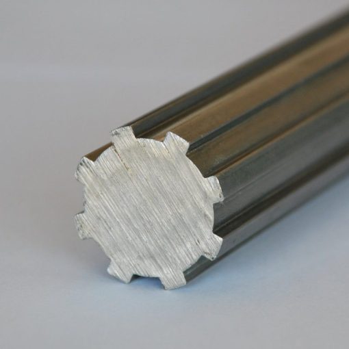
Un arbre cannelé est un composant mécanique constitué d'une série de cannelures usinées sur sa surface. Sa fonction principale est de transmettre le couple tout en permettant le mouvement relatif ou le glissement des pièces en contact. Voici une explication détaillée :
1. Structure et conception :
Un arbre cannelé présente généralement une forme cylindrique avec des cannelures externes ou internes. L'arbre à cannelures externes possède des cannelures sur sa surface extérieure, tandis que l'arbre à cannelures internes possède des cannelures à l'intérieur de son alésage. Le nombre, la taille et la forme des cannelures peuvent varier en fonction de l'application et des exigences de conception.
2. Transmission du couple :
La fonction principale d'un arbre cannelé est de transmettre le couple entre deux composants en prise, tels que des engrenages, des accouplements ou d'autres éléments rotatifs. Les cannelures de l'arbre s'engrènent avec les cannelures correspondantes du composant en prise, créant ainsi un verrouillage mécanique. Lorsqu'un couple est appliqué à l'arbre cannelé, l'engrènement des cannelures assure la transmission de la force de rotation de l'arbre au composant en prise, permettant ainsi au système de transmettre de la puissance.
3. Mouvement relatif :
Contrairement à d'autres types d'arbres, un arbre cannelé permet un mouvement relatif, ou glissement, entre l'arbre et la pièce en contact. Ce glissement peut être axial (le long de l'axe de l'arbre) ou radial (perpendiculaire à l'axe de l'arbre). Les cannelures assurent une interface précise et contrôlée qui permet ce mouvement tout en maintenant la transmission du couple. Cette caractéristique est particulièrement utile dans les applications où il est nécessaire de compenser un déplacement axial ou radial, ou un défaut d'alignement.
4. Répartition de la charge :
Une autre fonction importante d'un arbre cannelé est de répartir uniformément la charge appliquée sur sa longueur. Les cannelures créent de multiples points de contact entre l'arbre et la pièce en contact, ce qui contribue à répartir le couple et les forces axiales ou radiales sur une plus grande surface. Cette répartition de la charge minimise les concentrations de contraintes et réduit le risque d'usure prématurée ou de défaillance.
5. Polyvalence et applications :
Les arbres cannelés trouvent des applications dans divers secteurs et systèmes, notamment l'automobile, l'aérospatiale, la mécanique et la transmission de puissance. Ils sont couramment utilisés dans les boîtes de vitesses, les systèmes d'entraînement, les prises de force, les systèmes de direction et de nombreux autres mécanismes rotatifs où la transmission du couple, le mouvement relatif et la répartition de la charge sont essentiels.
6. Considérations de conception :
Lors de la conception d'un arbre cannelé, il est nécessaire de prendre en compte des facteurs tels que le couple requis, la vitesse, les charges appliquées et les conditions environnementales. La géométrie des cannelures, le choix des matériaux et l'état de surface sont essentiels pour garantir un bon engrènement, une capacité de charge adéquate et la durabilité de l'arbre.
En résumé, un arbre cannelé est un composant mécanique doté de cannelures permettant la transmission du couple tout en autorisant les mouvements relatifs ou le glissement entre les pièces en contact. Sa fonction principale est de transmettre la force de rotation, de répartir les charges et de permettre un déplacement axial ou radial dans diverses applications exigeant un transfert de couple précis et une grande flexibilité.


editor by CX 2023-10-24
Transformez le guide en demande de devis.
Veuillez envoyer le dessin technique, l'interface d'accouplement, les informations relatives à l'état du matériau et aux fonctions pour examen technique.
Demander un devis