Tag Archives: pulley price

China v-belt pulley sheaves wheel price v groove cast iron steel plastic nylon drive idler bearing sheaves pulley drive shaft parts

Warranty: 3 several years
Applicable Industries: Production Plant, Machinery Restore Outlets, Retail
Customized support: OEM, High quality motorbike sprocket 219 sprocket Double pitch big sprocket bicycle wheel ODM
Type: V-BELT
Content: Stainless steel
Merchandise title: v belt pulley
Software: Transmission
Colour: Black
Dimension: Stanard
Bore: Standard Bore Pulley
Area treatment method: Black Electrophoresis
Search term: Versatile Spline Shaft Coupling
Process: Sand Casting
Bore Kind: Taper Bushed Bore
Form: Spherical Condition
Packaging Details: opp bag+wooden case+pallet if required
Port: ZheJiang

V belt pulley sheaves wheel price v groove forged iron metal plastic nylon push idler bearing sheaves pulley Specification

Product identify v belt pulley
Materialcast metal
Europe commonSPA, SPB, SPC, TXIHU (WEST LAKE) DIS.G Substantial Pressure 30mpa 4500psi 300bar 220V PCP Paintball Electric powered Pump Air Compressor SPZ
Surface Treatment blackening
Balancestatic & dynamic
key phraseSPA pulley, Belt pulley
Packing & CZPT nozzle holdernozzle shaftsmt nozzle ball spline for CZPT YS24 device Supply FAQ one. what’t the moq 1pcs2. how several it take to submit solution about 1-3 monthsthree. technique of postment categorical, ship, Manufacturing unit Supplier Tailored Precision Spline ISO Certification machining Gear Generate Shaft air4. customized cargo can be made in accordance to your design and style

Analytical Approaches to Estimating Contact Pressures in Spline Couplings

A spline coupling is a type of mechanical connection between two rotating shafts. It consists of two parts – a coupler and a coupling. Both parts have teeth which engage and transfer loads. However, spline couplings are typically over-dimensioned, which makes them susceptible to fatigue and static behavior. Wear phenomena can also cause the coupling to fail. For this reason, proper spline coupling design is essential for achieving optimum performance.
splineshaft

Modeling a spline coupling

Spline couplings are becoming increasingly popular in the aerospace industry, but they operate in a slightly misaligned state, causing both vibrations and damage to the contact surfaces. To solve this problem, this article offers analytical approaches for estimating the contact pressures in a spline coupling. Specifically, this article compares analytical approaches with pure numerical approaches to demonstrate the benefits of an analytical approach.
To model a spline coupling, first you create the knowledge base for the spline coupling. The knowledge base includes a large number of possible specification values, which are related to each other. If you modify one specification, it may lead to a warning for violating another. To make the design valid, you must create a spline coupling model that meets the specified specification values.
After you have modeled the geometry, you must enter the contact pressures of the two spline couplings. Then, you need to determine the position of the pitch circle of the spline. In Figure 2, the centre of the male coupling is superposed to that of the female spline. Then, you need to make sure that the alignment meshing distance of the two splines is the same.
Once you have the data you need to create a spline coupling model, you can begin by entering the specifications for the interface design. Once you have this data, you need to choose whether to optimize the internal spline or the external spline. You’ll also need to specify the tooth friction coefficient, which is used to determine the stresses in the spline coupling model 20. You should also enter the pilot clearance, which is the clearance between the tip 186 of a tooth 32 on one spline and the feature on the mating spline.
After you have entered the desired specifications for the external spline, you can enter the parameters for the internal spline. For example, you can enter the outer diameter limit 154 of the major snap 54 and the minor snap 56 of the internal spline. The values of these parameters are displayed in color-coded boxes on the Spline Inputs and Configuration GUI screen 80. Once the parameters are entered, you’ll be presented with a geometric representation of the spline coupling model 20.

Creating a spline coupling model 20

The spline coupling model 20 is created by a product model software program 10. The software validates the spline coupling model against a knowledge base of configuration-dependent specification constraints and relationships. This report is then input to the ANSYS stress analyzer program. It lists the spline coupling model 20’s geometric configurations and specification values for each feature. The spline coupling model 20 is automatically recreated every time the configuration or performance specifications of the spline coupling model 20 are modified.
The spline coupling model 20 can be configured using the product model software program 10. A user specifies the axial length of the spline stack, which may be zero, or a fixed length. The user also enters a radial mating face 148, if any, and selects a pilot clearance specification value of 14.5 degrees or 30 degrees.
A user can then use the mouse 110 to modify the spline coupling model 20. The spline coupling knowledge base contains a large number of possible specification values and the spline coupling design rule. If the user tries to change a spline coupling model, the model will show a warning about a violation of another specification. In some cases, the modification may invalidate the design.
In the spline coupling model 20, the user enters additional performance requirement specifications. The user chooses the locations where maximum torque is transferred for the internal and external splines 38 and 40. The maximum torque transfer location is determined by the attachment configuration of the hardware to the shafts. Once this is selected, the user can click “Next” to save the model. A preview of the spline coupling model 20 is displayed.
The model 20 is a representation of a spline coupling. The spline specifications are entered in the order and arrangement as specified on the spline coupling model 20 GUI screen. Once the spline coupling specifications are entered, the product model software program 10 will incorporate them into the spline coupling model 20. This is the last step in spline coupling model creation.
splineshaft

Analysing a spline coupling model 20

An analysis of a spline coupling model consists of inputting its configuration and performance specifications. These specifications may be generated from another computer program. The product model software program 10 then uses its internal knowledge base of configuration dependent specification relationships and constraints to create a valid three-dimensional parametric model 20. This model contains information describing the number and types of spline teeth 32, snaps 34, and shoulder 36.
When you are analysing a spline coupling, the software program 10 will include default values for various specifications. The spline coupling model 20 comprises an internal spline 38 and an external spline 40. Each of the splines includes its own set of parameters, such as its depth, width, length, and radii. The external spline 40 will also contain its own set of parameters, such as its orientation.
Upon selecting these parameters, the software program will perform various analyses on the spline coupling model 20. The software program 10 calculates the nominal and maximal tooth bearing stresses and fatigue life of a spline coupling. It will also determine the difference in torsional windup between an internal and an external spline. The output file from the analysis will be a report file containing model configuration and specification data. The output file may also be used by other computer programs for further analysis.
Once these parameters are set, the user enters the design criteria for the spline coupling model 20. In this step, the user specifies the locations of maximum torque transfer for both the external and internal spline 38. The maximum torque transfer location depends on the configuration of the hardware attached to the shafts. The user may enter up to four different performance requirement specifications for each spline.
The results of the analysis show that there are two phases of spline coupling. The first phase shows a large increase in stress and vibration. The second phase shows a decline in both stress and vibration levels. The third stage shows a constant meshing force between 300N and 320N. This behavior continues for a longer period of time, until the final stage engages with the surface.
splineshaft

Misalignment of a spline coupling

A study aimed to investigate the position of the resultant contact force in a spline coupling engaging teeth under a steady torque and rotating misalignment. The study used numerical methods based on Finite Element Method (FEM) models. It produced numerical results for nominal conditions and parallel offset misalignment. The study considered two levels of misalignment – 0.02 mm and 0.08 mm – with different loading levels.
The results showed that the misalignment between the splines and rotors causes a change in the meshing force of the spline-rotor coupling system. Its dynamics is governed by the meshing force of splines. The meshing force of a misaligned spline coupling is related to the rotor-spline coupling system parameters, the transmitting torque, and the dynamic vibration displacement.
Despite the lack of precise measurements, the misalignment of splines is a common problem. This problem is compounded by the fact that splines usually feature backlash. This backlash is the result of the misaligned spline. The authors analyzed several splines, varying pitch diameters, and length/diameter ratios.
A spline coupling is a two-dimensional mechanical system, which has positive backlash. The spline coupling is comprised of a hub and shaft, and has tip-to-root clearances that are larger than the backlash. A form-clearance is sufficient to prevent tip-to-root fillet contact. The torque on the splines is transmitted via friction.
When a spline coupling is misaligned, a torque-biased thrust force is generated. In such a situation, the force can exceed the torque, causing the component to lose its alignment. The two-way transmission of torque and thrust is modeled analytically in the present study. The analytical approach provides solutions that can be integrated into the design process. So, the next time you are faced with a misaligned spline coupling problem, make sure to use an analytical approach!
In this study, the spline coupling is analyzed under nominal conditions without a parallel offset misalignment. The stiffness values obtained are the percentage difference between the nominal pitch diameter and load application diameter. Moreover, the maximum percentage difference in the measured pitch diameter is 1.60% under a torque of 5000 N*m. The other parameter, the pitch angle, is taken into consideration in the calculation.

China v-belt pulley sheaves wheel price v groove cast iron steel plastic nylon drive idler bearing sheaves pulley     drive shaft parts	China v-belt pulley sheaves wheel price v groove cast iron steel plastic nylon drive idler bearing sheaves pulley     drive shaft parts
editor by czh 2023-02-24

China Spline Shaft for Timing Pulley Bar Stock with ce certificate top quality Good price

Merchandise Description

CZPT Timing belt pulley bar stock gives the conclude user the potential to construct their personal pulleys.  Specifically for those who need CZPT , value-powerful prototypes. 

 
Our bar stock is CZPT in Metric and Inch sizes,
·         HTD3M, 5M, 8M
·         MXL,XL,L
·         T2.5, T5, T10 AT5, AT10
·         Much more pitches on demand.
 
The most generally utilized material:
C45E and CZPT


Approach Products Precision Diploma Machining range
Blank Making Resin bonded sand production lineVertical parting flaskless molding line,146 opening manufacturing lineElectric furnace CZPT cupola Guillotine shear,Punching device Forge rolling device CZPT die forging equipment precision forged precision forging precision molding All kinds of casting and forging parts
Warmth Therapy Vertical furnace Speckled furnaceHigh frequency quenching furnace Substance hardness transformation≤HRC1 Hardening and Tempering Quenching CZPT frequency quenching Carburizing and quenching
Machining Specific NC equipment Dimesion tolerance 6 diploma Roughness Ra0.8 Roundness,straightness and concentricity accuracy≤0.01mm internal hole≥5mm, outside diameter ≤800mm
Grinding machining NC excircle grinding device Surface grinding device Dimesion precision 5 diploma Roughness Ra0.four Outside the house diameter 3mm to 320mm
Teeth-profile Creating NC equipment hobbing maching equipment slotting machine Roughness Ra1.6 Concentricity .05 Maximum module M=ten, OD≤1800mm
Hobbing and drilling CNC machinedrilling machineNC milling equipment Hole dimesion tolerance 6 degree positioning accuracy .05 Workbench leghth 1650mm width 852mm bare minimum diameter 1mm
Other Machining Hydraulic broaching equipment sawing machine punching machine lather labeling equipment keyway tolerance 7 degree symmetry diploma .05 spline straight keyway spline keyway
Floor Remedy sprucing machine plating production line spray-painting linecoating lineoxidizing line phosphating line In accordance with CZPT pean normal RoHS. Surface polishing Cr6+totally free zinc plating,Nickle challenging chromium Decorative chrome platingNicklePaiting phosphating AnodizingblackeningDacrotized

The tractor’s brief shaft, commonly referred to as the PTO, transmits electricity from the tractor to the PTO-pushed device or instrument. Electricity transfer is attained by connecting the machine’s driveshaft to the tractor’s PTO stub shaft. The PTO and driveshaft had been operate at 540 rpm (9 cycles/sec) or one thousand rpm (sixteen.6 cycles/sec). At any velocity, their rotation is proportional to the velocity of the tractor motor. Most incidents involving PTO stubs are because of to apparel being caught by a occupied but unsuspecting PTO stub. Causes a PTO stub might stay engaged contain: the operator forgets or does not know the PTO clutch is engaged sees the PTO stub spinning but thinks it is not hazardous adequate to launch it, or the operator is engaged in function activities. Shoelaces, pant legs, overalls and coveralls, sweatshirts, and trench coats are clothes that can be grabbed and wrapped all around spinning PTO spools.

Wholesale made in China – replacement parts – in Bordeaux France Price Timing Belt Pulley for 3D Printer China Factory with ce certificate top quality low price

Wholesale  made in China - replacement parts -  in Bordeaux France  Price Timing Belt Pulley for 3D Printer China Factory with ce certificate top quality low price

Wholesale  made in China - replacement parts -  in Bordeaux France  Price Timing Belt Pulley for 3D Printer China Factory with ce certificate top quality low price

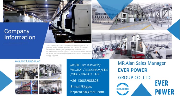
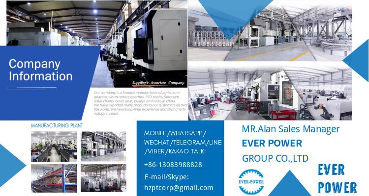
We – EPG Group the bigge EPT Chain and agricultural gearbox manufacturing facility in China with 5 diverse branches. For far more particulars: Cellular/whatsapp/telegram/Kakao us at: 0086~13083988828 13858117778 0571 88828

Wholesale value Timing Belt Pulley for 3D printer China Factory

Synchronous PULLEY custom-made by HangZhou Manufactuer.

Main Functions:
1. EPT tooth number from fourteen to seventy two timing pulley
2. Materials can be developed by customer prerequisite
three. Substantial torque collection S2M S3M S5M S8M P2M P3M P5M P8M 
four. Standard torque collection MXL XL L H 
5. Substantial precision drive sequence  2GT 3GT 5GT 8YU
six. Gentle load drive series T5 T10
7. Heave load generate series AT5 AT10
eight. Clamping Timing Pulleys S3M S5M S8M

Sort Timing pulley adapt to 1/4 inch, 5/sixteen inch, 3/8 inch, 12 inch belt.
Specification Standard or Personalized made
Material Stainless steel,,brass, carbon metal, aluminum, and so on.
Machining Method Equipment Hobbing, Equipment Milling, Gear Shaping, Equipment Broaching,Gear Shaving, Equipment Grinding and Equipment Lapping
Floor Treatment Zn-plating, Ni-plating, Cr-plating, Tin-plating, Copper-plating, the wreath oxygen resin spraying, black oxide coating, portray, powdering, colour zinc-plated,blue black zinc-plated, silver plating,anodizing etc.
Producing Equipment CNC device , automatic lathe machine,stamping device,CNC milling equipment,rolling machine, lasering, tag grinding device and so on.
Administration Technique ISO9001 – 2008
Tests Equipment Projecting apparatus, Salt Spray Test, Durometer, and Coating thickness tester, 2nd projector

Condition Choice:

Pulley Manufacturing Workshop and Software:

Purposes Toy, Automotive, instrument, electrical equipment, family appliances, household furniture, mechanical tools,daily dwelling products, digital sporting activities equipment, , sanitation machinery, market/ resort equipment provides, and so on.

Our Organization:
HangZhou Hefa Gear EPT Co.,L EPT established in 2009, is a expert manufacture engaged in advancement, creation, income and support of timing pulley, precise spur gears, helical gears, bevel equipment, worm& worm gear and so on. We located in HangZhou with hassle-free transposition excite. Hefa Gear EPT focused to rigorous good quality control and thoughtful buyer support. Our experienced staffs are often offered to examine your specifications, and satisfy your gratification.
Creation approach: Molding Chopping, Equipment Hobbing, Gear Milling, Gear Shaping, Gear Broaching,Equipment Shaving, Gear Grinding and Equipment Lapping.

Inspection:
Hefa Gear EPT committed to stringent top quality control.” Focus and Expert on the Development of EPT Discipline”  this is Hefa Equipment EPT goal. Perform stage by action, Hefa always give accomplishment solution in precise conveyor area. Giving be EPT price, tremendous provider and standard delivery are always our priorities.

Packaging, Stock and Delivery:

Packaging Polyethylene bag or oil paper for each item
Pile on carton or as customer’s demand from customers
Supply of Samples By DHL, Fedex, UPS,  TNT, EMS
Guide time 10-fifteen functioning times as normal, 30days in active season, it will based mostly on the thorough order quantity.

FAQ:

Major Marketplaces? North The usa, South The us, EPT Europe , We EPT Europe , North Europe, South Europe, Asia
How to buy? * You ship us drawing or sample
* We carry via venture assessment
* We give you our layout for your confirmation
* We make the sample and deliver it to you soon after you confirmed our design and style
* You confirm the sample then area an buy and pay out us 30% deposit
* We begin producing
* When the products is accomplished, you pay us the harmony soon after you verified photographs or tracking quantities.
* Trade is accomplished, thank you!!

Positive aspects:

  1. High temperature resistance.Self lubrication.Wear resistance.Flame retardant qualities.


The use of first equipment manufacturer’s (OEM) portion figures or logos , e.g. CASE® and John Deere® are for reference functions only and for indicating product use and compatibility. Our firm and the outlined substitute parts contained herein are not sponsored, accredited, or created by the OEM.

Wholesale  made in China - replacement parts -  in Bordeaux France  Price Timing Belt Pulley for 3D Printer China Factory with ce certificate top quality low price

Wholesale  made in China - replacement parts -  in Bordeaux France  Price Timing Belt Pulley for 3D Printer China Factory with ce certificate top quality low price

Wholesale  made in China - replacement parts -  in Bordeaux France  Price Timing Belt Pulley for 3D Printer China Factory with ce certificate top quality low price

OEM price made in China – replacement parts – in Hanoi Viet Nam Belt Pulley for Engine Parts by Powder Metallurgy with top quality

OEM  price  made in China - replacement parts -  in Hanoi Viet Nam  Belt Pulley for Engine Parts by Powder Metallurgy with top quality

We – EPG Team the bigge EPT gearbox & motors , vee pulleys, timing pulleys, couplings and gears manufacturing unit in China with 5 various branches. For far more information: Cellular/whatsapp/telegram/Kakao us at: 0086~13083988828 13858117778 0571 88828

EPT Belt Pulley for EngineParts by powder metallurgy

Merchandise Identify areas by powder metallurgy
Substance Iron powder, alloy powder,treasured metal powder
Technology Sintering – Powder Metallurgy
  Certification ISO9001/TS16949
Floor Treatment Large frequency quenching, oil impregnation,CNC,vacuum cleaning,sharpening,
Apperance No crumbling, cracks, exfoliation, voids, metallic pitting and EPT problems
 
Procedure Flow
Powder mixing – Forming – Sintering – Oil impregnation – Sizing -Ultrasonic cleaning – Steam oxidation – Oil impregnation – Ultimate inspection – Packing
Software EPT parts, automobile areas, Power Tools parts, Motor parts, electric Bicycle

Why Powdered Metals?

Important co EPT savings.
Generate complicated or special styles.
No or minimum squander during creation.
Substantial good quality completed products.
Energy of components

Generation approach of powder metallurgy
Powder mixing – Forming – Sintering – Oil impregnation – Sizing -Ultrasonic cleansing – Steam oxidation – Oil impregnation – Last inspection – Packing
 

Organization Profile
JINGSHI established in 2007                                               
Maker & Exporter                             
Exacting in generating powder metallurgy gears and parts    
Handed ISO/TS16949 High quality Certification                  
Superior Equipment                                
Numbers senior R & D engineers and Skilled operators      
Precise Examination Instruments.                        
Strict High quality Control                                 
With the “Far more range, A lot more excellent, A lot more skilled ” business needs, we are fully commited to create prolonged-expression friendship and get-get connection with domestic and worldwide clients to create a brilliant future .
 
Remember to Send us your Second or 3D drawings to start off our cooperation!


We – EPG Group the bigge EPT gearbox & motors , vee pulleys, timing pulleys, couplings and gears manufacturing facility in China with 5 distinct branches. For far more specifics: Mobile/whatsapp/telegram/Kakao us at: 0086~13083988828 13858117778 0571 88828 The use of first gear manufacturer’s (OEM) part quantities or emblems , e.g. CASE® and John Deere® are for reference purposes only and for indicating item use and compatibility. Our business and the listed substitute areas contained herein are not sponsored, approved, or created by the OEM.

OEM  price  made in China - replacement parts -  in Hanoi Viet Nam  Belt Pulley for Engine Parts by Powder Metallurgy with top quality

OEM  price  made in China - replacement parts -  in Hanoi Viet Nam  Belt Pulley for Engine Parts by Powder Metallurgy with top quality