Como Ler o Ângulo de Pressão em um Desenho de Eixo Estriado — O ângulo de pressão descreve a orientação dos flancos dos dentes de trabalho e é um requisito de compatibilidade de acoplamento. Duas estrias com a mesma quantidade de dentes e diâmetro semelhante ainda podem ser incompatíveis se seus ângulos de pressão ou sistemas de dentes forem diferentes; portanto, o ângulo deve ser lido no desenho ou verificado por meio de geometria confiável, em vez de inferido pela aparência.
Para ângulo de pressão do eixo estriadoA especificação mais confiável é aquela que um projetista, comprador, fabricante e inspetor podem interpretar da mesma maneira. A discussão a seguir se concentra em entradas de desenho mensuráveis, condições de montagem e verificações práticas, em vez de alegações universais de torque, ajuste ou vida útil que não podem ser determinadas sem dados completos de geometria e condição de uso.
Ângulo de pressão conforme a geometria do flanco do dente
Ângulo de pressão conforme a geometria do flanco do dente Controla a orientação dos flancos de trabalho. Uma incompatibilidade pode impedir o engate adequado ou deslocar o contato em direção a uma aresta, mesmo quando o número de dentes parece correto. Considere o ângulo de pressão como um parâmetro de compatibilidade que deve estar de acordo nos elementos externos e internos.
Ao realizar engenharia reversa, não infira o ângulo a partir de uma fotografia. Verifique-o com medições confiáveis, uma peça correspondente ou um desenho original. O método de inspeção deve ser capaz de distinguir o sistema de dentes especificado, em vez de apenas verificar o diâmetro externo.
Como o ângulo afeta a compatibilidade de acasalamento
Como o ângulo afeta a compatibilidade de acasalamento Afeta a área de contato, a sensação de montagem e a distribuição da carga. O engate efetivo é o comprimento ao longo do qual os flancos dos dentes podem efetivamente suportar carga; chanfros, alívios e porções incompletas dos dentes não devem ser automaticamente considerados como comprimento de trabalho.
O encaixe deve ser avaliado como um par de peças acopladas. Espessura do dente, largura do espaço, folgas de diâmetro, alinhamento e temperatura contribuem para isso. Para substituições, inspecione ambas as peças, pois o desgaste no cubo pode fazer com que um novo eixo pareça solto, mesmo quando a nova estria externa estiver dentro da tolerância do desenho. Para este tópico, relacione essa decisão ao componente acoplado e à revisão do desenho usada para a solicitação de cotação. Ao revisar o ângulo de pressão do eixo estriado, revise este ponto sempre que o componente acoplado, a condição do material ou a condição de operação mudarem.
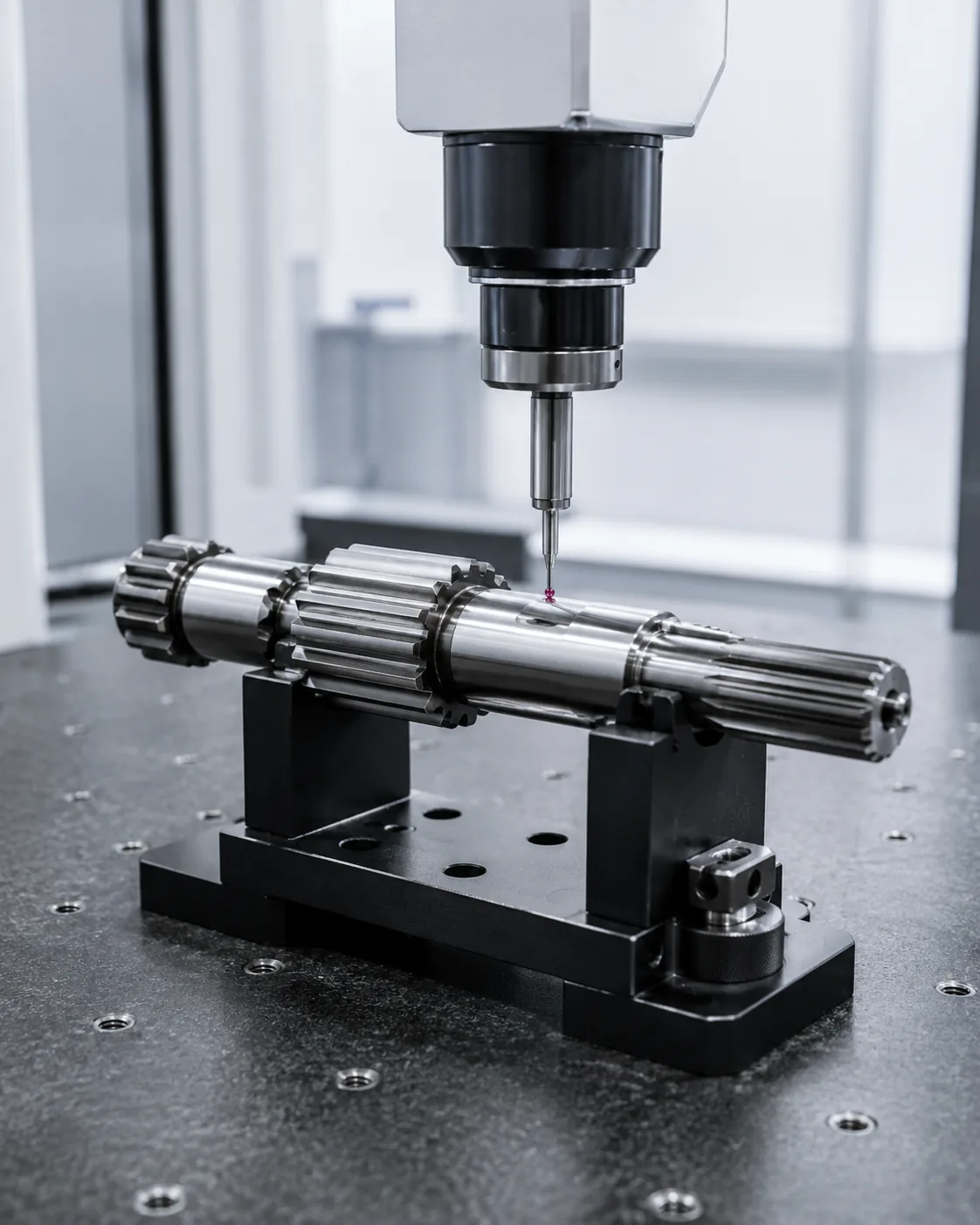
Por que o ângulo não pode ser inferido pela aparência?
Por que o ângulo não pode ser inferido pela aparência? Deve-se analisar o contexto do ângulo de pressão do eixo estriado. Identifique o componente de acoplamento, a função operacional e a característica do desenho que essa decisão controla. O requisito deve ser mensurável e estar relacionado ao ajuste, à transferência de torque, ao alinhamento, ao desgaste ou a outra necessidade de montagem definida.
Considere a decisão juntamente com a condição do material, a sequência de fabricação e o acesso para inspeção. Se a peça for de reposição, compare a geometria da peça não desgastada com a do componente de acoplamento, em vez de copiar o dano. Para novos projetos, mantenha as opções de processo flexíveis, a menos que um processo específico seja exigido pelo próprio projeto. Nesta análise, o critério de aceitação útil é aquele que pode ser rastreado até uma característica funcional do desenho. Em uma solicitação de cotação (RFQ) para ângulo de pressão de um eixo estriado, mantenha esse ponto vinculado ao componente de acoplamento, ao esquema de referência e ao método de aceitação da peça acabada.
Chamada de desenho e base padrão
Chamada de desenho e base padrão Deve-se analisar o contexto do ângulo de pressão do eixo estriado. Identifique o componente de acoplamento, a função operacional e a característica do desenho que essa decisão controla. O requisito deve ser mensurável e estar relacionado ao ajuste, à transferência de torque, ao alinhamento, ao desgaste ou a outra necessidade de montagem definida.
Considere a decisão juntamente com a condição do material, a sequência de fabricação e o acesso para inspeção. Se a peça for de reposição, compare a geometria da peça não desgastada com a da peça de acoplamento, em vez de copiar os danos. Para novos projetos, mantenha as opções de processo flexíveis, a menos que um processo específico seja exigido pelo próprio projeto. Para trabalhos repetidos, mantenha o mesmo datum e a mesma base de medição, a menos que o requisito de montagem mude. Em uma solicitação de cotação (RFQ) para ângulo de pressão de eixo estriado, mantenha este ponto vinculado à peça de acoplamento, ao esquema de datum e ao método de aceitação da peça acabada.
Consequências da Inspeção
Consequências da Inspeção Deve-se utilizar um método que meça a característica do desenho de forma direta ou funcional. Calibradores funcionais, medição analítica de dentes, inspeção por CMM, medições de vão e medições sobre pinos ou esferas respondem a perguntas diferentes e não são intercambiáveis por padrão.
Defina o método antes da produção quando a tolerância for apertada ou quando o cliente e o fornecedor utilizarem equipamentos diferentes. Controle a temperatura, a limpeza e a calibração dos instrumentos de medição para garantir a repetibilidade. O relatório de inspeção deve identificar a revisão do desenho e a configuração de referência para que lotes posteriores possam ser comparados com base nos mesmos critérios. Quando a função ou o elemento de acoplamento mudar, revise este ponto em vez de manter a suposição anterior. Em uma solicitação de cotação (RFQ) para ângulo de pressão de um eixo estriado, mantenha este ponto vinculado ao elemento de acoplamento, ao esquema de referência e ao método de aceitação da peça acabada.

Verificação de peças de reposição
Verificação de peças de reposição Deve-se analisar o contexto do ângulo de pressão do eixo estriado. Identifique o componente de acoplamento, a função operacional e a característica do desenho que essa decisão controla. O requisito deve ser mensurável e estar relacionado ao ajuste, à transferência de torque, ao alinhamento, ao desgaste ou a outra necessidade de montagem definida.
Considere a decisão juntamente com a condição do material, a sequência de fabricação e o acesso para inspeção. Se a peça for de reposição, compare a geometria da peça não desgastada com a do componente de acoplamento, em vez de copiar os danos. Para novos projetos, mantenha as opções de processo flexíveis, a menos que um processo específico seja exigido pelo próprio projeto. Para este tópico, relacione essa decisão ao componente de acoplamento e à revisão do desenho utilizada na solicitação de cotação. Ao revisar o ângulo de pressão do eixo estriado, revisite este ponto sempre que o componente de acoplamento, a condição do material ou a condição operacional forem alterados.
Uma sequência de revisão prática
Uma sequência prática de revisão começa com o componente de acoplamento e o caminho do torque, confirmando em seguida o sistema de dentes, o engate e as características do eixo que definem a conexão. Depois, define-se o material e o tratamento térmico, os acabamentos funcionais e quaisquer requisitos de excentricidade ou posicionamento. Nesta revisão, o critério de aceitação útil é aquele que pode ser rastreado até uma característica funcional do desenho. Ao revisar o ângulo de pressão do eixo estriado, revisite este ponto sempre que o componente de acoplamento, a condição do material ou a condição de operação mudarem.
Finalize acordando o método de inspeção, a quantidade e a documentação da primeira peça. Essa ordem impede que decisões sobre o processo ou tolerância sejam tomadas antes que a interface funcional seja compreendida e facilita a comparação de orçamentos, pois as mesmas informações de projeto são apresentadas a cada fornecedor. Para trabalhos repetidos, mantenha o mesmo datum e base de medição, a menos que o requisito de montagem mude. Para saber como ler o ângulo de pressão em um desenho de eixo estriado, aplique esta verificação à interface específica do ângulo de pressão do eixo estriado mostrada no desenho atual.
Interação com o módulo e contagem de dentes
Interação com o módulo e contagem de dentes Define parte da geometria do dente de acoplamento. O módulo ou passo define o tamanho do dente, enquanto a quantidade de dentes contribui para o diâmetro primitivo e a indexação circunferencial. Esses valores devem corresponder à estria oposta; devem ser lidos no desenho controlado ou verificados na geometria original, em vez de estimados a partir do diâmetro total do eixo.
Complete a definição com o ângulo de pressão, diâmetros maior e menor, espessura do dente ou largura do espaço, comprimento de engate e a base de ajuste ou tolerância aplicável. O fornecedor também precisa dos diâmetros e referências adjacentes, pois o acesso às ferramentas e a configuração de inspeção dependem de todo o eixo, não apenas dos dentes. Quando a função ou o elemento de acoplamento mudar, revise este ponto em vez de manter a suposição anterior.
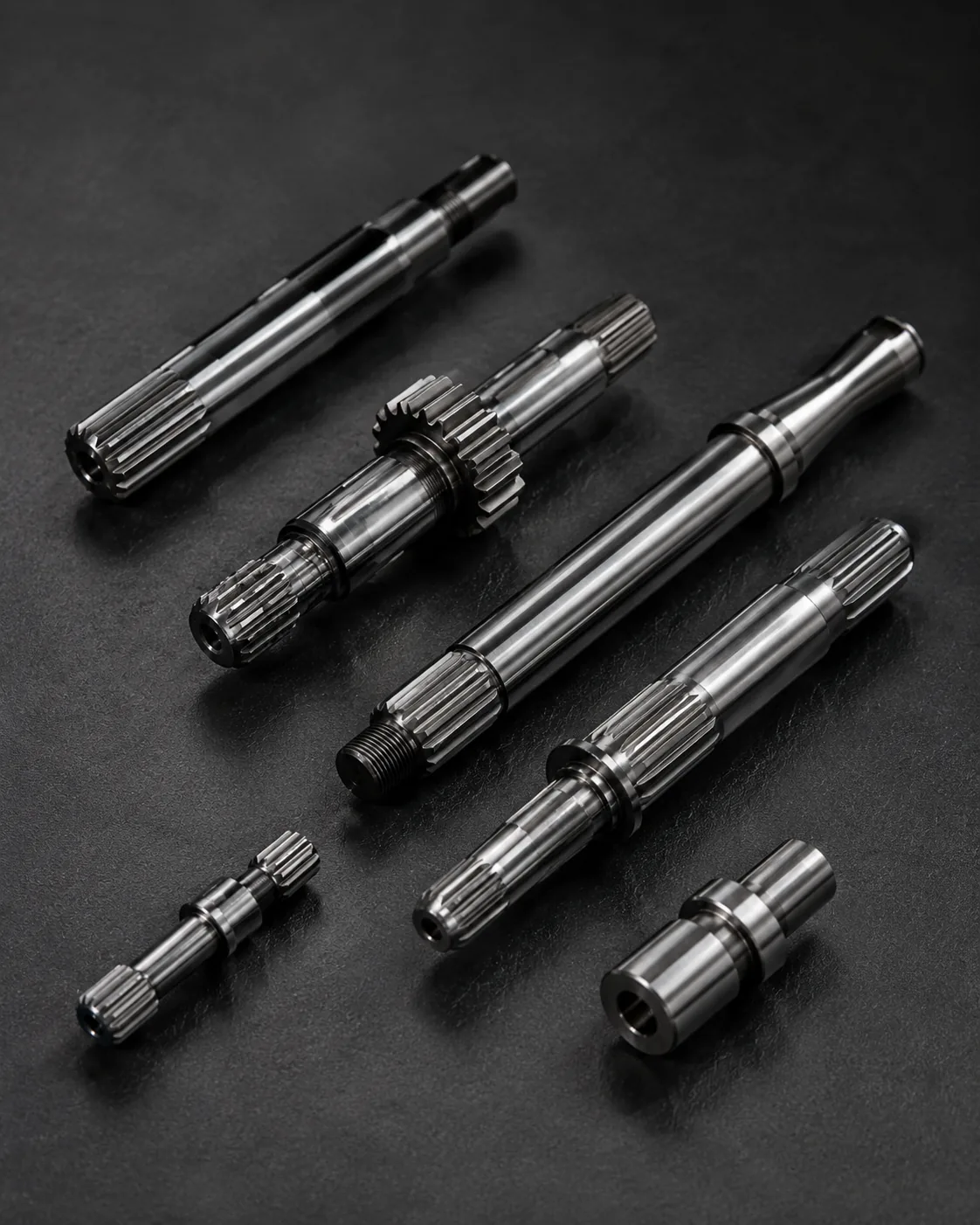
Evitando chamadas de sistemas mistos
Evitando chamadas de sistemas mistos Deve-se analisar o contexto do ângulo de pressão do eixo estriado. Identifique o componente de acoplamento, a função operacional e a característica do desenho que essa decisão controla. O requisito deve ser mensurável e estar relacionado ao ajuste, à transferência de torque, ao alinhamento, ao desgaste ou a outra necessidade de montagem definida.
Considere a decisão juntamente com a condição do material, a sequência de fabricação e o acesso para inspeção. Se a peça for de reposição, compare a geometria da peça não desgastada com a do componente de acoplamento, em vez de copiar os danos. Para novos projetos, mantenha as opções de processo flexíveis, a menos que um processo específico seja exigido pelo próprio projeto. Para este tópico, vincule essa decisão ao componente de acoplamento e à revisão do desenho usada na solicitação de cotação. Para "Como ler o ângulo de pressão em um desenho de eixo estriado", registre o requisito resultante no desenho ou na especificação de compra para que permaneça consistente em pedidos subsequentes.
Erros comuns a evitar
Erros comuns no ângulo de pressão de eixos estriados decorrem do tratamento de um único valor nominal como se definisse toda a interface. Ângulo de pressão ausente, referências pouco claras, dimensões de desgaste copiadas, localização da dureza não especificada e métodos de inspeção incompatíveis podem resultar em peças que parecem corretas no papel, mas que não se montam de forma consistente.
Uma revisão mais eficaz começa com o par de acoplamento, identifica o caminho da carga e os pontos de referência, e então conecta a geometria, a condição do material e a inspeção a essas funções. Resolva as dúvidas no desenho antes da produção e mantenha a interpretação acordada na revisão para pedidos subsequentes. Nesta revisão, o critério de aceitação útil é aquele que pode ser rastreado até uma característica funcional do desenho. Para a leitura do ângulo de pressão em um desenho de eixo estriado, registre o requisito resultante no desenho ou na especificação de compra para que permaneça consistente em pedidos subsequentes.
Resumo da decisão
| Área de decisão | O que confirmar | Por que isso importa |
|---|---|---|
| Geometria de acoplamento | Sistema dentário, diâmetros, encaixe e ajuste | Compatibilidade de controles e contato lateral |
| Localização | Datums, diários, ombros e batimento | Controla o alinhamento na montagem |
| Condições do material | Grau, tratamento térmico, dureza e acabamento | Define a condição mecânica e de desgaste final. |
| Obrigação | Torque, velocidade, impacto, movimento e ambiente | Conecta a definição da peça às condições de operação. |
| Inspeção | Características controladas e método de medição | Mantém a aceitação consistente entre fornecedor e comprador. |
Lista de verificação de especificações
- Componente de acoplamento e orientação externa/interna do dente
- Sistema de módulo ou passo, número de dentes, ângulo de pressão e diâmetros maior/menor
- Engate efetivo, ajuste ou tolerância e movimento axial, se necessário.
- Material, tratamento térmico, localização da dureza e acabamentos superficiais funcionais.
- Requisitos de referência, diâmetros de rolamento ou piloto, excentricidade e localização axial
- Torque, velocidade, carga de choque ou reversa, lubrificação e ambiente operacional.
- Quantidade, requisitos do primeiro artigo e documentação de inspeção acordada
Use o gama de produtos de eixos estriados para comparar as configurações disponíveis e o Lista de verificação para desenho de RFQ Para preparar uma consulta completa. Para trabalhos repetidos, mantenha o mesmo datum e base de medição, a menos que o requisito de montagem mude. Para Como Ler o Ângulo de Pressão em um Desenho de Eixo Estriado, registre o requisito resultante no desenho ou na especificação de compra para que permaneça consistente em pedidos repetidos.
Planilha de engenharia para ângulo de pressão do eixo estriado
Use esta folha de exercícios para transformar Como Ler o Ângulo de Pressão em um Desenho de Eixo Estriado em decisões que podem ser mostradas em um desenho, verificadas durante a cotação e confirmadas na primeira peça. Comece com Ângulo de pressão conforme a geometria do flanco do dente e Como o ângulo afeta a compatibilidade de acasalamento, porque esses dois itens geralmente definem a geometria de acoplamento ou a condição do material que o restante do processo deve suportar. Em seguida, revise Por que o ângulo não pode ser inferido pela aparência?, Chamada de desenho e base padrão e Consequências da Inspeção em relação ao conjunto real, em vez de tratá-los como valores de catálogo independentes.
Para um problema de seleção, escreva a peça de acoplamento e o caminho de carga na parte superior da folha de trabalho. Identifique quais superfícies posicionam o eixo, se a estria é fixa ou deslizante, a direção de montagem e o engate efetivo dos dentes. Registre o módulo ou sistema de passo, a quantidade de dentes, o ângulo de pressão e os limites de diâmetro a partir do desenho técnico. Se o projeto for novo, mantenha as opções de ajuste e tolerância vinculadas à função requerida; se a peça for de reposição, compare o elemento de acoplamento com as regiões não desgastadas antes de definir a geometria nominal. Para a leitura do ângulo de pressão em um desenho de eixo estriado, registre o requisito resultante no desenho ou na especificação de compra para que permaneça consistente em pedidos subsequentes.
Em seguida, explique por que o ângulo não pode ser inferido pela aparência e qual característica do desenho ele se destina a controlar. Um instrumento de medição funcional pode responder a uma pergunta diferente da medição analítica de dentes ou da inspeção por CMM, portanto, a solicitação de cotação não deve simplesmente solicitar uma “inspeção completa”. Indique quais características são importantes para a montagem, qual referência de datum é utilizada e se um relatório de primeira peça é necessário. Isso facilita a comparação das cotações dos fornecedores, pois cada fornecedor analisa a mesma definição de interface.
Sequência de revisão de desenhos
Antes de solicitar a produção, revise o desenho na mesma ordem em que a montagem funciona: sistema de encaixe dos dentes, engate eficaz, pontos de referência de localização, mancais ou ressaltos adjacentes, material e tratamento térmico, acabamentos funcionais e método de inspeção. ângulo de pressão do eixo estriadoA ordem é importante porque decisões posteriores, como a seleção do processo ou a escolha do instrumento de medição, devem dar suporte à interface, em vez de redefini-la.
| Item da folha de exercícios | Pergunta a responder | Saída da RFQ |
|---|---|---|
| Ângulo de pressão conforme a geometria do flanco do dente | Que função de montagem este recurso controla? | Dimensão, tolerância ou referência de acoplamento |
| Como o ângulo afeta a compatibilidade de acasalamento | Que condição final deve ser alcançada? | Descrição do material/tratamento térmico/acabamento |
| Por que o ângulo não pode ser inferido pela aparência? | Como essa característica será verificada? | Método de inspeção ou nota de relatório |
| Chamada de desenho e base padrão | Como o membro oposto interage? | Informações sobre partes do acasalamento e noivado |
| Consequências da Inspeção | Qual dado estabelece a localização funcional? | Relação entre datum e runout |
Transferência de responsabilidade para o processo de aquisição antes da primeira peça.
Um pacote de compras útil para Como Ler o Ângulo de Pressão em um Desenho de Eixo Estriado Contém o desenho controlado, a quantidade, o material e as condições de tratamento térmico, as informações da interface de acoplamento e as características de aceitação que exigem relatório. Se um modelo 3D for fornecido, o desenho 2D ainda deverá conter as tolerâncias, referências, notas sobre o tratamento térmico e os requisitos de inspeção. Identifique a revisão atual na solicitação de cotação para que a fabricação e a inspeção não trabalhem com versões diferentes.
Quando uma característica ainda não foi definida, marque-a para esclarecimento técnico em vez de inserir um valor conveniente. Para o ângulo de pressão de um eixo estriado, os itens em aberto comuns são: engate, ajuste, localização da dureza, excentricidade em relação a um munhão adjacente, acesso a características internas ou a condição de um componente de acoplamento desgastado. Resolver esses pontos antes da primeira peça reduz retrabalho desnecessário e facilita o controle de pedidos subsequentes.
Lista de verificação pré-lançamento
- Confirme o ângulo de pressão em relação à geometria do flanco do dente e ao componente de acoplamento real.
- Confirme como o ângulo afeta a compatibilidade de acasalamento na condição final.
- Defina como será feita a análise que demonstra por que o ângulo não pode ser inferido pela aparência.
- Verifique as especificações do desenho e a base padrão sob a condição de montagem pretendida.
- Relacione as consequências da inspeção com a estrutura de dados funcionais.
- Indique a quantidade, o nível de revisão e quaisquer requisitos de documentação do primeiro artigo.
- Registre as alterações de serviço, lubrificação ou componentes de acoplamento para pedidos repetidos.
Perguntas frequentes
O que devo confirmar sobre o ângulo de pressão em relação à geometria do flanco do dente para o ângulo de pressão de um eixo estriado?
Primeiramente, relacione o ângulo de pressão como geometria do flanco do dente com o componente de acoplamento e a função de montagem. Inclua o requisito mensurável no desenho controlado e, quando a compatibilidade depender de ambas as peças, inclua o componente oposto. Para a interpretação do ângulo de pressão em um desenho de eixo estriado, isso evita que uma etiqueta nominal substitua a geometria que realmente controla o encaixe e a transferência de torque.
O que devo confirmar sobre como o ângulo afeta a compatibilidade de acoplamento para o ângulo de pressão do eixo estriado?
Confirme como o ângulo afeta a compatibilidade de acoplamento na condição final, incluindo qualquer material, tratamento térmico, superfície ou estado dimensional que possa mudar após o processamento. Se o requisito depender de uma localização ou referência, mostre isso explicitamente para que a produção e a inspeção usem a mesma referência.
O que devo confirmar sobre o motivo pelo qual o ângulo não pode ser inferido da aparência para o ângulo de pressão do eixo estriado?
Escolha um método de inspeção que meça a característica especificada no desenho. Medição funcional, medição analítica de estrias, verificações por CMM, inspeção de excentricidade, medição de rugosidade e teste de dureza respondem a diferentes perguntas. Indique qual resultado é necessário para a aceitação, em vez de solicitar um relatório de inspeção genérico. Ao revisar o ângulo de pressão do eixo estriado, revise este ponto sempre que o componente de acoplamento, a condição do material ou a condição de operação mudarem.
O que devo confirmar sobre a indicação no desenho e a base padrão para o ângulo de pressão do eixo estriado?
Verifique as especificações do desenho e a base padrão com a peça de acoplamento real e as condições de montagem previstas. O engate efetivo, a folga, o movimento axial, a temperatura e o desgaste em um cubo de substituição podem influenciar o comportamento da conexão. Um novo eixo não deve ser aceito ou rejeitado apenas pela sensação tátil quando houver um requisito de ajuste mensurável.
O que devo confirmar sobre as consequências da inspeção do ângulo de pressão do eixo estriado?
Associe as consequências da inspeção às características que determinam a rotação na montagem. O desenho deve deixar clara a referência de datum e qualquer relação de excentricidade ou posição. Se o tratamento térmico ou o acabamento da usinagem puderem deslocar a característica, inspecione a relação na etapa que representa a peça acabada.
Da decisão de engenharia ao controle de produção
Uma vez definida a interface, traduza cada decisão funcional em uma característica de desenho que possa ser fabricada e inspecionada. Evite deixar relações importantes apenas em anotações de e-mail. Dimensões, referências, condições de tratamento térmico e requisitos de aceitação devem ser controlados por revisão para que a equipe de produção e a equipe de inspeção trabalhem com a mesma definição. Nesta revisão, o critério de aceitação útil é aquele que pode ser rastreado até uma característica funcional do desenho. Para saber como ler o ângulo de pressão em um desenho de eixo estriado, aplique esta verificação à interface específica do ângulo de pressão do eixo estriado mostrada no desenho atual.
Para as primeiras peças, priorize as características que comprovam a compatibilidade da montagem: geometria dos dentes, ajuste de acoplamento, relação com os mancais ou ressaltos de localização, condição do tratamento térmico e qualquer excentricidade crítica. Registre o método de medição juntamente com o resultado. Em pedidos repetidos, usar a mesma configuração de referência e abordagem de medição facilita o reconhecimento de mudanças de tendência e reduz as disputas causadas por diferentes interpretações de inspeção. Para trabalhos repetidos, mantenha a mesma referência e base de medição, a menos que o requisito de montagem mude. Em uma solicitação de cotação (RFQ) para ângulo de pressão de eixo estriado, mantenha este ponto vinculado ao elemento de acoplamento, ao esquema de referência e ao método de aceitação da peça acabada.
Quando a aplicação operacional muda, reabra a revisão de engenharia em vez de presumir que a especificação antiga continua adequada. Torque mais elevado, maior impacto, inversões mais frequentes, lubrificação diferente ou um novo componente de acoplamento podem alterar o contato e o desgaste, mesmo que a dimensão nominal da estria permaneça a mesma. O desenho deve evoluir com os requisitos reais de montagem. Quando a aplicação operacional ou o componente de acoplamento mudarem, revise este ponto em vez de manter a suposição anterior. Ao revisar o ângulo de pressão do eixo estriado, revise este ponto sempre que o componente de acoplamento, a condição do material ou a aplicação operacional mudarem.
Prepare a solicitação de cotação (RFQ).
- Desenho 2D atual e revisão
- Componente de acoplamento e definição de spline
- Materiais, tratamento térmico e acabamentos funcionais
- Torque, velocidade, ciclo de trabalho e ambiente
- Quantidade e documentação de inspeção necessária
Uma solicitação de cotação completa combina o desenho, a interface de acoplamento, a condição do material, a aplicação, a quantidade e as expectativas de inspeção. Quando esses dados são definidos antecipadamente, os fornecedores podem planejar as ferramentas, o tratamento térmico, o acabamento e a medição em torno do mesmo requisito funcional, reduzindo os ciclos de esclarecimento antes da primeira peça. Para este tópico, relacione essa decisão ao componente de acoplamento e à revisão do desenho usada na solicitação de cotação. Para "Como ler o ângulo de pressão em um desenho de eixo estriado", aplique esta verificação à interface específica do ângulo de pressão do eixo estriado mostrada no desenho atual.
Transforme o guia em uma solicitação de cotação (RFQ).
Envie o desenho controlado, a interface de acoplamento, as condições do material e as informações sobre a capacidade de processamento para análise técnica.
Solicite um orçamento