Bagaimana Modul dan Jumlah Gigi Menentukan Antarmuka Poros Spline — Modul dan jumlah gigi bekerja bersama untuk menentukan ukuran gigi dan geometri pitch dasar dari spline metrik. Keduanya harus sesuai persis dengan komponen pasangannya, dan keduanya saja tidak cukup: sudut tekanan, diameter mayor dan minor, ketebalan gigi atau lebar ruang, dan keterlibatan masih perlu ditentukan untuk antarmuka yang lengkap.
Untuk jumlah gigi modul poros splineSpesifikasi yang paling dapat diandalkan adalah spesifikasi yang dapat diinterpretasikan dengan cara yang sama oleh perancang, pembeli, produsen, dan inspektur. Pembahasan di bawah ini berfokus pada masukan gambar yang terukur, kondisi perakitan, dan pemeriksaan praktis, bukan pada klaim torsi, kesesuaian, atau masa pakai universal yang tidak dapat ditentukan tanpa data geometri dan beban kerja yang lengkap.
Modul atau Jarak Antar Gigi sebagai Definisi Ukuran Gigi
Modul atau Jarak Antar Gigi sebagai Definisi Ukuran Gigi Menentukan bagian dari geometri gigi yang berpasangan. Modul atau pitch menentukan ukuran gigi, sedangkan jumlah gigi berkontribusi pada diameter pitch dan pengindeksan keliling. Nilai-nilai ini harus sesuai dengan spline yang berlawanan; nilai-nilai tersebut harus dibaca dari gambar yang terkontrol atau diverifikasi dari geometri yang tidak aus, bukan diperkirakan dari diameter poros keseluruhan.
Lengkapi definisi dengan sudut tekanan, diameter mayor dan minor, ketebalan gigi atau lebar ruang, panjang kontak, dan dasar kesesuaian atau toleransi yang berlaku. Pemasok juga membutuhkan diameter dan datum yang berdekatan karena akses perkakas dan pengaturan inspeksi bergantung pada seluruh poros, bukan hanya giginya. Untuk topik ini, hubungkan keputusan tersebut dengan komponen pasangannya dan revisi gambar yang digunakan untuk RFQ.
Hubungan Jumlah Gigi dan Diameter Pitch
Hubungan Jumlah Gigi dan Diameter Pitch Menentukan bagian dari geometri gigi yang berpasangan. Modul atau pitch menentukan ukuran gigi, sedangkan jumlah gigi berkontribusi pada diameter pitch dan pengindeksan keliling. Nilai-nilai ini harus sesuai dengan spline yang berlawanan; nilai-nilai tersebut harus dibaca dari gambar yang terkontrol atau diverifikasi dari geometri yang tidak aus, bukan diperkirakan dari diameter poros keseluruhan.
Lengkapi definisi dengan sudut tekanan, diameter mayor dan minor, ketebalan gigi atau lebar ruang, panjang kontak, dan dasar kesesuaian atau toleransi yang berlaku. Pemasok juga membutuhkan diameter dan datum yang berdekatan karena akses perkakas dan pengaturan inspeksi bergantung pada seluruh poros, bukan hanya giginya. Dalam tinjauan ini, kriteria penerimaan yang berguna adalah kriteria yang dapat ditelusuri ke karakteristik gambar fungsional.
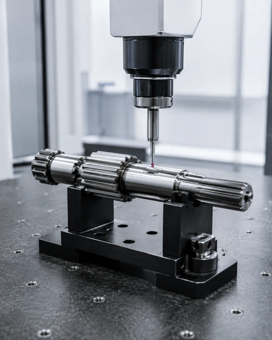
Diameter Mayor dan Minor
Diameter Mayor dan Minor Hal ini perlu ditinjau dalam konteks jumlah gigi modul poros spline. Identifikasi komponen yang berpasangan, fungsi pengoperasian, dan fitur gambar yang dikendalikan oleh keputusan ini. Persyaratan tersebut harus terukur dan terkait dengan kesesuaian, transfer torsi, penyelarasan, keausan, atau kebutuhan perakitan lain yang telah ditentukan.
Pertimbangkan keputusan tersebut bersamaan dengan kondisi material, urutan manufaktur, dan akses inspeksi. Jika komponen tersebut merupakan pengganti, bandingkan geometri yang tidak aus dan komponen pasangannya alih-alih meniru kerusakan. Untuk desain baru, pertahankan pilihan proses yang fleksibel kecuali jika proses spesifik itu sendiri diperlukan oleh desain. Untuk pekerjaan berulang, pertahankan datum dan dasar pengukuran yang sama kecuali jika persyaratan perakitan berubah. Saat meninjau jumlah gigi modul poros spline, tinjau kembali poin ini setiap kali komponen pasangannya, kondisi material, atau beban operasi berubah.
Kompatibilitas Bagian yang Saling Berpasangan
Kompatibilitas Bagian yang Saling Berpasangan Hal ini memengaruhi area kontak, rasa perakitan, dan distribusi beban. Keterlibatan efektif adalah panjang di mana sisi gigi benar-benar dapat menahan beban; chamfer, relief, dan bagian gigi yang tidak lengkap tidak boleh secara otomatis dihitung sebagai panjang kerja.
Kecocokan harus dievaluasi sebagai sepasang komponen yang saling berpasangan. Ketebalan gigi, lebar ruang, jarak diameter, keselarasan, dan suhu semuanya berkontribusi. Untuk penggantian, periksa kedua bagian karena keausan pada hub dapat membuat poros baru terasa longgar meskipun spline eksternal baru berada dalam toleransi gambarnya. Ketika tugas atau komponen yang berpasangan berubah, tinjau kembali poin ini alih-alih melanjutkan asumsi sebelumnya. Saat meninjau jumlah gigi modul poros spline, tinjau kembali poin ini setiap kali komponen yang berpasangan, kondisi material, atau tugas pengoperasian berubah.
Keterlibatan dan Pembagian Beban
Keterlibatan dan Pembagian Beban Hal ini memengaruhi area kontak, rasa perakitan, dan distribusi beban. Keterlibatan efektif adalah panjang di mana sisi gigi benar-benar dapat menahan beban; chamfer, relief, dan bagian gigi yang tidak lengkap tidak boleh secara otomatis dihitung sebagai panjang kerja.
Kecocokan harus dievaluasi sebagai sepasang komponen yang saling berpasangan. Ketebalan gigi, lebar ruang, jarak diameter, keselarasan, dan suhu semuanya berkontribusi. Untuk penggantian, periksa kedua bagian karena keausan pada hub dapat membuat poros baru terasa longgar meskipun spline eksternal baru berada dalam toleransi gambarnya. Untuk topik ini, hubungkan keputusan tersebut dengan komponen yang berpasangan dan revisi gambar yang digunakan untuk RFQ. Saat meninjau jumlah gigi modul poros spline, tinjau kembali poin ini setiap kali komponen yang berpasangan, kondisi material, atau tugas pengoperasian berubah.
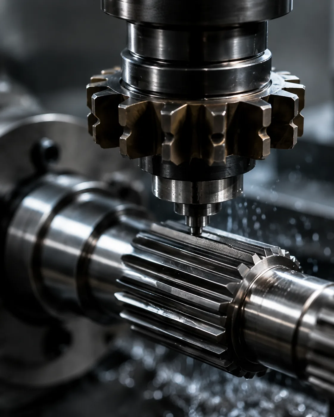
Pengukuran Melalui Gigi atau Penggunaan Alat Ukur
Pengukuran Melalui Gigi atau Penggunaan Alat Ukur Sebaiknya gunakan metode yang mengukur karakteristik gambar secara langsung atau fungsional. Alat ukur fungsional, pengukuran gigi analitis, inspeksi CMM, pengukuran rentang, dan pengukuran di atas pin atau bola menjawab pertanyaan yang berbeda dan tidak dapat saling menggantikan secara otomatis.
Sepakati metode sebelum produksi ketika toleransi ketat atau ketika pelanggan dan pemasok menggunakan peralatan yang berbeda. Kendalikan suhu, kebersihan, dan kalibrasi alat ukur untuk memastikan pengulangan. Laporan inspeksi harus mengidentifikasi revisi gambar dan pengaturan datum sehingga lot selanjutnya dapat dibandingkan berdasarkan dasar yang sama. Dalam tinjauan ini, kriteria penerimaan yang berguna adalah kriteria yang dapat ditelusuri ke karakteristik gambar fungsional. Dalam permintaan penawaran (RFQ) jumlah gigi modul poros spline, kaitkan poin ini dengan anggota pasangannya, skema datum, dan metode penerimaan bagian jadi.
Urutan tinjauan praktis
Urutan peninjauan praktis dimulai dengan komponen pasangan dan jalur torsi, kemudian mengkonfirmasi sistem gigi, keterlibatan, dan fitur poros yang menentukan lokasi sambungan. Selanjutnya, tentukan material dan perlakuan panas, penyelesaian fungsional, dan persyaratan runout atau posisi apa pun. Untuk pekerjaan berulang, pertahankan datum dan dasar pengukuran yang sama kecuali jika persyaratan perakitan berubah. Dalam permintaan penawaran (RFQ) jumlah gigi modul poros spline, kaitkan poin ini dengan anggota pasangan, skema datum, dan metode penerimaan bagian jadi.
Akhiri dengan menyepakati metode inspeksi, kuantitas, dan dokumentasi artikel pertama. Urutan ini mencegah pengambilan keputusan proses atau toleransi sebelum antarmuka fungsional dipahami dan membuat penawaran lebih mudah dibandingkan karena masukan desain yang sama disajikan kepada setiap pemasok. Ketika tugas atau anggota pasangannya berubah, tinjau kembali poin ini alih-alih meneruskan asumsi sebelumnya. Dalam permintaan penawaran (RFQ) jumlah gigi modul poros spline, kaitkan poin ini dengan anggota pasangannya, skema datum, dan metode penerimaan bagian jadi.
Konsistensi Penayangan Gambar
Konsistensi Penayangan Gambar Hal ini perlu ditinjau dalam konteks jumlah gigi modul poros spline. Identifikasi komponen yang berpasangan, fungsi pengoperasian, dan fitur gambar yang dikendalikan oleh keputusan ini. Persyaratan tersebut harus terukur dan terkait dengan kesesuaian, transfer torsi, penyelarasan, keausan, atau kebutuhan perakitan lain yang telah ditentukan.
Pertimbangkan keputusan tersebut bersama dengan kondisi material, urutan manufaktur, dan akses inspeksi. Jika komponen tersebut merupakan pengganti, bandingkan geometri yang tidak aus dan komponen pasangannya alih-alih meniru kerusakan. Untuk desain baru, jaga agar pilihan proses tetap fleksibel kecuali jika proses spesifik itu sendiri diperlukan oleh desain. Untuk topik ini, hubungkan keputusan tersebut dengan komponen pasangannya dan revisi gambar yang digunakan untuk RFQ. Dalam RFQ jumlah gigi modul poros spline, kaitkan poin ini dengan komponen pasangannya, skema datum, dan metode penerimaan komponen jadi.
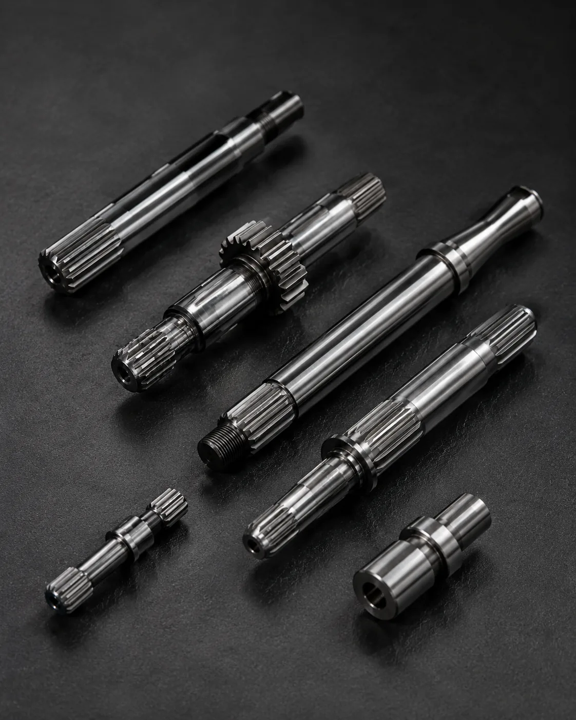
Mengapa Diameter Poros Nominal Tidak Cukup?
Mengapa Diameter Poros Nominal Tidak Cukup? Hal ini perlu ditinjau dalam konteks jumlah gigi modul poros spline. Identifikasi komponen yang berpasangan, fungsi pengoperasian, dan fitur gambar yang dikendalikan oleh keputusan ini. Persyaratan tersebut harus terukur dan terkait dengan kesesuaian, transfer torsi, penyelarasan, keausan, atau kebutuhan perakitan lain yang telah ditentukan.
Pertimbangkan keputusan tersebut bersamaan dengan kondisi material, urutan manufaktur, dan akses inspeksi. Jika komponen tersebut merupakan pengganti, bandingkan geometri yang tidak aus dan komponen pasangannya alih-alih meniru kerusakan. Untuk desain baru, pertahankan pilihan proses yang fleksibel kecuali jika proses spesifik itu sendiri diperlukan oleh desain. Dalam tinjauan ini, kriteria penerimaan yang berguna adalah kriteria yang dapat ditelusuri ke karakteristik gambar fungsional. Saat meninjau jumlah gigi modul poros spline, tinjau kembali poin ini setiap kali komponen pasangannya, kondisi material, atau tugas pengoperasian berubah.
Kesalahan umum yang harus dihindari
Kesalahan umum dalam penghitungan gigi modul poros spline berasal dari memperlakukan satu nilai nominal seolah-olah nilai tersebut mendefinisikan antarmuka secara keseluruhan. Sudut tekanan yang hilang, datum yang tidak jelas, dimensi keausan yang disalin, lokasi kekerasan yang tidak ditentukan, dan metode inspeksi yang tidak sesuai dapat menghasilkan komponen yang tampak benar di atas kertas tetapi tidak dapat dirakit secara konsisten.
Tinjauan yang lebih baik dimulai dengan pasangan yang saling berpasangan, mengidentifikasi jalur beban dan fitur penempatan, kemudian menghubungkan geometri, kondisi material, dan inspeksi dengan fungsi-fungsi tersebut. Tutup pertanyaan yang belum terjawab pada gambar sebelum produksi dan pertahankan interpretasi yang disepakati dengan revisi untuk pesanan berulang. Untuk pekerjaan berulang, pertahankan datum dan dasar pengukuran yang sama kecuali jika persyaratan perakitan berubah. Untuk Bagaimana Modul dan Jumlah Gigi Mendefinisikan Antarmuka Poros Spline, terapkan pemeriksaan ini pada antarmuka jumlah gigi modul poros spline spesifik yang ditunjukkan pada gambar saat ini.
Ringkasan keputusan
| Area pengambilan keputusan | Apa yang perlu dikonfirmasi | Mengapa ini penting |
|---|---|---|
| Geometri perkawinan | Sistem gigi, diameter, keterlibatan, dan kesesuaian. | Kompatibilitas kontrol dan kontak samping |
| Lokasi | Datum, jurnal, bahu, dan runout | Mengontrol keselarasan dalam perakitan |
| Kondisi material | Kelas, perlakuan panas, kekerasan, dan penyelesaian | Menentukan kondisi mekanis dan keausan akhir. |
| Tugas | Torsi, kecepatan, guncangan, gerakan, dan lingkungan | Menghubungkan definisi komponen dengan kondisi pengoperasian. |
| Inspeksi | Karakteristik terkontrol dan metode pengukuran | Menjaga konsistensi penerimaan antara pemasok dan pembeli. |
Daftar periksa spesifikasi
- Komponen pasangan dan orientasi gigi eksternal/internal
- Modul atau sistem pitch, jumlah gigi, sudut tekanan, dan diameter mayor/minor.
- Keterlibatan yang efektif, kesesuaian atau dasar toleransi, dan pergerakan aksial jika diperlukan.
- Material, perlakuan panas, lokasi kekerasan, dan lapisan permukaan fungsional.
- Datum, diameter bantalan atau pilot, runout, dan persyaratan lokasi aksial.
- Torsi, kecepatan, beban kejut atau beban balik, pelumasan, dan lingkungan pengoperasian.
- Jumlah, persyaratan artikel pertama, dan dokumentasi inspeksi yang disepakati.
Gunakan rangkaian produk poros spline untuk membandingkan konfigurasi yang tersedia dan Daftar periksa gambar RFQ untuk menyiapkan penyelidikan lengkap. Ketika tugas atau anggota pasangan berubah, tinjau kembali poin ini alih-alih meneruskan asumsi sebelumnya. Untuk Bagaimana Modul dan Jumlah Gigi Mendefinisikan Antarmuka Poros Spline, terapkan pemeriksaan ini pada antarmuka jumlah gigi modul poros spline spesifik yang ditunjukkan pada gambar saat ini.
Lembar kerja teknik untuk penghitungan gigi modul poros spline
Gunakan lembar kerja ini untuk beralih Bagaimana Modul dan Jumlah Gigi Menentukan Antarmuka Poros Spline menjadi keputusan yang dapat ditunjukkan pada gambar, diperiksa selama penawaran harga, dan diverifikasi pada artikel pertama. Mulailah dengan Modul atau Jarak Antar Gigi sebagai Definisi Ukuran Gigi Dan Hubungan Jumlah Gigi dan Diameter Pitch, karena kedua hal tersebut biasanya menentukan geometri penyambungan atau kondisi material yang harus didukung oleh proses selanjutnya. Kemudian tinjau Diameter Mayor dan Minor, Kompatibilitas Bagian yang Saling Berpasangan Dan Keterlibatan dan Pembagian Beban terhadap susunan sebenarnya daripada memperlakukannya sebagai nilai katalog independen.
Untuk masalah pemilihan, tulis bagian yang berpasangan dan jalur beban di bagian atas lembar kerja. Identifikasi permukaan mana yang menempatkan poros, apakah spline tetap atau geser, arah perakitan, dan keterlibatan gigi yang efektif. Catat modul atau sistem pitch, jumlah gigi, sudut tekanan, dan batas diameter dari gambar kontrol. Jika desainnya baru, pastikan pilihan kesesuaian dan toleransi terkait dengan fungsi yang dibutuhkan; jika bagian tersebut merupakan pengganti, bandingkan anggota yang berpasangan dan area yang tidak aus sebelum menentukan geometri nominal. Saat meninjau jumlah gigi modul poros spline, tinjau kembali poin ini setiap kali komponen yang berpasangan, kondisi material, atau tugas pengoperasian berubah.
Selanjutnya, hubungkan diameter mayor dan minor dengan karakteristik gambar yang ingin dikontrol. Alat ukur fungsional dapat menjawab pertanyaan yang berbeda dari pengukuran gigi analitis atau inspeksi CMM, jadi RFQ tidak boleh hanya meminta "inspeksi lengkap". Nyatakan fitur mana yang penting untuk perakitan, referensi datum apa yang digunakan, dan apakah laporan artikel pertama diperlukan. Hal ini membuat penawaran pemasok lebih mudah dibandingkan karena setiap pemasok meninjau definisi antarmuka yang sama.
Urutan tinjauan gambar
Sebelum meminta produksi, tinjau gambar dengan urutan yang sama seperti pengerjaan perakitan: sistem gigi yang saling berpasangan, keterlibatan yang efektif, titik acuan, jurnal atau bahu yang berdekatan, material dan perlakuan panas, lapisan akhir fungsional, dan metode inspeksi. Untuk jumlah gigi modul poros splineUrutan tersebut penting karena keputusan selanjutnya, seperti pemilihan proses atau pilihan alat ukur, harus mendukung antarmuka tersebut, bukan mendefinisikannya ulang.
| Item lembar kerja | Pertanyaan untuk dijawab | Keluaran RFQ |
|---|---|---|
| Modul atau Jarak Antar Gigi sebagai Definisi Ukuran Gigi | Fungsi perakitan apa yang dikendalikan oleh fitur ini? | Dimensi, toleransi, atau referensi pemasangan. |
| Hubungan Jumlah Gigi dan Diameter Pitch | Kondisi akhir apa yang harus dicapai? | Keterangan material / perlakuan panas / finishing |
| Diameter Mayor dan Minor | Bagaimana karakteristik tersebut akan diverifikasi? | Metode inspeksi atau catatan pelaporan |
| Kompatibilitas Bagian yang Saling Berpasangan | Bagaimana tanggapan anggota lawan? | Informasi bagian perkawinan dan keterlibatan |
| Keterlibatan dan Pembagian Beban | Data mana yang menentukan lokasi fungsional? | Hubungan datum dan runout |
Pengalihan pengadaan sebelum artikel pertama
Paket pembelian yang bermanfaat untuk Bagaimana Modul dan Jumlah Gigi Menentukan Antarmuka Poros Spline Berisi gambar terkontrol, kuantitas, material dan kondisi perlakuan panas, informasi antarmuka sambungan, dan karakteristik penerimaan yang perlu dilaporkan. Jika model 3D disediakan, gambar 2D tetap harus memuat toleransi, datum, catatan perlakuan panas, dan persyaratan inspeksi. Identifikasi revisi terkini dalam RFQ agar manufaktur dan inspeksi tidak menggunakan versi yang berbeda.
Jika suatu karakteristik belum ditentukan, tandai untuk klarifikasi teknis daripada memasukkan nilai yang mudah. Untuk jumlah gigi modul poros spline, hal-hal yang umum perlu dipertimbangkan adalah keterlibatan, kesesuaian, lokasi kekerasan, penyimpangan terhadap jurnal yang berdekatan, akses fitur internal, atau kondisi komponen pasangan yang aus. Menyelesaikan poin-poin tersebut sebelum artikel pertama mengurangi pengerjaan ulang yang tidak perlu dan membuat pesanan berulang selanjutnya lebih mudah dikendalikan.
Daftar periksa pra-rilis
- Konfirmasikan modul atau jarak antar gigi sebagai definisi ukuran gigi terhadap komponen pasangannya yang sebenarnya.
- Konfirmasikan hubungan antara jumlah gigi dan diameter pitch pada kondisi akhir.
- Jelaskan bagaimana diameter mayor dan minor akan diperiksa.
- Periksa kompatibilitas komponen yang akan dipasangkan dalam kondisi perakitan yang dimaksud.
- Kaitkan keterlibatan dan pembagian beban dengan struktur data fungsional.
- Sebutkan jumlah, tingkat revisi, dan persyaratan dokumentasi artikel pertama.
- Catat perubahan pada tugas, pelumasan, atau perangkat keras yang saling berhubungan untuk pesanan berulang.
Pertanyaan yang sering diajukan
Apa yang perlu saya konfirmasi mengenai modul atau pitch sebagai definisi ukuran gigi untuk jumlah gigi modul poros spline?
Pertama-tama, kaitkan modul atau pitch sebagai definisi ukuran gigi dengan komponen pasangannya dan fungsi perakitan. Cantumkan persyaratan terukur pada gambar terkontrol, dan sertakan anggota yang berlawanan ketika kompatibilitas bergantung pada kedua bagian. Untuk bagaimana modul dan jumlah gigi mendefinisikan antarmuka poros spline, ini mencegah label nominal menggantikan geometri yang sebenarnya mengontrol kesesuaian dan transfer torsi.
Apa yang perlu saya konfirmasi tentang hubungan antara jumlah gigi dan diameter pitch untuk jumlah gigi modul poros spline?
Konfirmasikan hubungan antara jumlah gigi dan diameter pitch pada kondisi akhir, termasuk setiap perubahan material, perlakuan panas, permukaan, atau dimensi yang dapat berubah setelah pemrosesan. Jika persyaratan bergantung pada lokasi atau titik acuan, tunjukkan secara eksplisit agar produksi dan inspeksi menggunakan referensi yang sama.
Apa yang perlu saya konfirmasi mengenai diameter mayor dan minor untuk jumlah gigi modul poros spline?
Pilih metode inspeksi yang mengukur karakteristik yang disebutkan pada gambar. Pengukuran fungsional, pengukuran spline analitik, pemeriksaan CMM, inspeksi runout, pengukuran kekasaran, dan pengujian kekerasan menjawab pertanyaan yang berbeda. Nyatakan hasil mana yang diperlukan untuk penerimaan daripada meminta laporan inspeksi umum. Untuk Bagaimana Modul dan Jumlah Gigi Mendefinisikan Antarmuka Poros Spline, terapkan pemeriksaan ini pada antarmuka jumlah gigi modul poros spline spesifik yang ditunjukkan pada gambar saat ini.
Apa yang perlu saya konfirmasi mengenai kompatibilitas bagian yang saling berpasangan untuk jumlah gigi modul poros spline?
Periksa kompatibilitas bagian yang akan dipasangkan dengan bagian yang sebenarnya dan kondisi perakitan yang dimaksud. Keterlibatan yang efektif, celah, pergerakan aksial, suhu, dan keausan pada hub pengganti semuanya dapat memengaruhi perilaku sambungan. Poros baru tidak boleh diterima atau ditolak hanya berdasarkan perasaan saja ketika persyaratan kecocokan yang terukur tersedia.
Apa yang perlu saya konfirmasi mengenai keterkaitan dan pembagian beban untuk jumlah gigi modul poros spline?
Kaitkan keterlibatan dan pembagian beban dengan fitur-fitur yang menentukan rotasi dalam perakitan. Gambar harus memperjelas referensi datum dan setiap penyimpangan atau hubungan posisi. Jika perlakuan panas atau pemesinan akhir dapat menggeser fitur tersebut, periksa hubungannya pada tahap yang mewakili bagian yang sudah jadi.
Dari pengambilan keputusan teknik hingga pengendalian produksi
Setelah antarmuka disepakati, terjemahkan setiap keputusan fungsional ke dalam karakteristik gambar yang dapat diproduksi dan diperiksa. Hindari hanya mencantumkan hubungan kunci dalam catatan email. Dimensi, datum, kondisi perlakuan panas, dan persyaratan penerimaan harus dikontrol revisinya sehingga tim produksi dan tim inspeksi bekerja dengan definisi yang sama. Untuk pekerjaan berulang, pertahankan datum dan dasar pengukuran yang sama kecuali jika persyaratan perakitan berubah. Dalam permintaan penawaran (RFQ) jumlah gigi modul poros spline, kaitkan poin ini dengan anggota pasangannya, skema datum, dan metode penerimaan bagian jadi.
Untuk artikel pertama, prioritaskan karakteristik yang membuktikan kompatibilitas perakitan: geometri gigi, kesesuaian pemasangan, hubungan dengan jurnal atau bahu penempatan, kondisi perlakuan panas, dan setiap penyimpangan kritis. Catat metode pengukuran bersama dengan hasilnya. Pada pesanan berulang, menggunakan pengaturan datum dan pendekatan pengukuran yang sama memudahkan pengenalan perubahan tren dan mengurangi perselisihan yang disebabkan oleh interpretasi inspeksi yang berbeda. Ketika tugas atau anggota pasangan berubah, tinjau kembali poin ini alih-alih melanjutkan asumsi sebelumnya. Untuk Bagaimana Modul dan Jumlah Gigi Mendefinisikan Antarmuka Poros Spline, catat persyaratan yang dihasilkan pada gambar atau spesifikasi pembelian agar tetap konsisten pada pesanan berulang.
Ketika tugas pengoperasian berubah, buka kembali tinjauan teknik alih-alih menganggap spesifikasi lama tetap sesuai. Torsi yang lebih tinggi, peningkatan guncangan, pembalikan yang lebih sering, pelumasan yang berbeda, atau komponen pasangan baru dapat mengubah kontak dan keausan meskipun ukuran spline nominal tetap sama. Gambar harus berkembang sesuai dengan persyaratan perakitan aktual. Untuk topik ini, hubungkan keputusan tersebut dengan komponen pasangan dan revisi gambar yang digunakan untuk RFQ. Untuk Bagaimana Modul dan Jumlah Gigi Mendefinisikan Antarmuka Poros Spline, terapkan pemeriksaan ini pada antarmuka jumlah gigi modul poros spline spesifik yang ditunjukkan pada gambar saat ini.
Siapkan RFQ (Permintaan Penawaran).
- Gambar 2D terkini dan revisi
- Komponen pasangan dan definisi spline
- Bahan, perlakuan panas, dan lapisan fungsional
- Torsi, kecepatan, beban kerja, dan lingkungan.
- Jumlah dan dokumen inspeksi yang dibutuhkan
Permintaan penawaran yang lengkap menggabungkan gambar, antarmuka pasangan, kondisi material, tugas, kuantitas, dan harapan inspeksi. Ketika masukan ini didefinisikan sejak awal, pemasok dapat merencanakan perkakas, perlakuan panas, penyelesaian akhir, dan pengukuran berdasarkan persyaratan fungsional yang sama, mengurangi siklus klarifikasi sebelum artikel pertama. Dalam tinjauan ini, kriteria penerimaan yang berguna adalah kriteria yang dapat ditelusuri ke karakteristik gambar fungsional. Dalam permintaan penawaran (RFQ) jumlah gigi modul poros spline, kaitkan poin ini dengan anggota pasangan, skema datum, dan metode penerimaan bagian jadi.
Ubah panduan ini menjadi Permintaan Penawaran (RFQ).
Kirim gambar terkontrol, antarmuka pemasangan, kondisi material, dan informasi tugas untuk tinjauan teknis.
Permintaan Penawaran